GD&T Basics for Engineers Who Don't Want to Read the Full ASME Standard
A practical, example-driven walkthrough of geometric dimensioning and tolerancing: the 14 symbols, what datums actually do, and when GD&T is worth the extra drawing complexity versus a plain ± tolerance.
- Author:
- Cadagen
- Technical review:
- CADAGEN Engineering Team · Mechanical Engineer
- Last updated:
- August 16, 2026
- Sources:
- 4 primary references, listed below
GD&T (Geometric Dimensioning and Tolerancing) is a symbolic language, standardized in ASME Y14.5-2018 (R2024), for specifying how much a part's shape, orientation, and location are allowed to vary — in a way that maps directly to how the part actually functions, instead of just how it measures on a flat ruler. The short version: plain ± tolerances control size; GD&T controls form, orientation, and location, which is usually what actually determines whether a part assembles and works. The 2018 revision also emphasizes profile for locating surfaces and clarifies datum degrees of freedom for model-based (MBD) drawings — not only orthographic paper drawings.
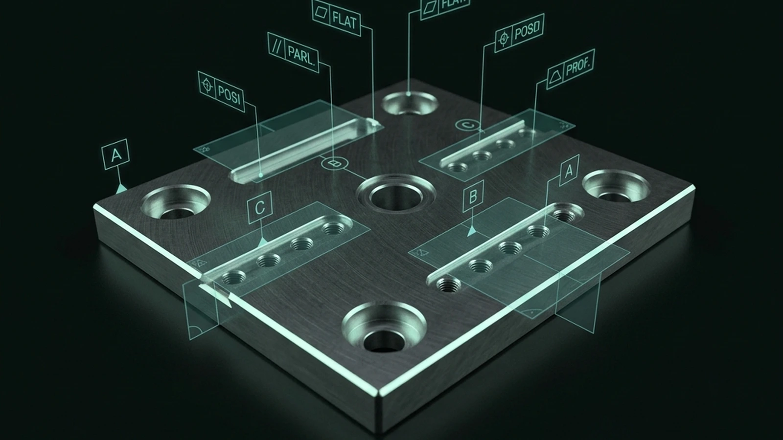
The 14 symbols, grouped by what they control
ASME Y14.5-2018 organizes its 14 geometric characteristic symbols into five families. You don't need to memorize all 14 to use GD&T well — you need to understand the five families and reach for the specific symbol only when a plain tolerance genuinely can't say what you mean.
| Family | Symbols | Controls | Needs a datum? |
|---|---|---|---|
| Form | Straightness, Flatness, Circularity, Cylindricity | How much a single feature can deviate from its ideal shape | No |
| Profile | Profile of a Line, Profile of a Surface | How much a curve or surface can deviate from its ideal (often nominal CAD) form | Optional (with or without datum reference) |
| Orientation | Perpendicularity, Parallelism, Angularity | Angle of a feature relative to a datum | Yes |
| Location | Position, Concentricity, Symmetry | Location of a feature relative to a datum | Yes |
| Runout | Circular Runout, Total Runout | Combined form/location deviation as a part rotates about a datum axis | Yes |
The rule that resolves most confusion: form controls never reference a datum, because they describe a feature's shape relative to itself. Everything else needs at least one datum, because orientation, location, and runout are meaningless without something to measure "relative to."
What a datum actually is (and isn't)
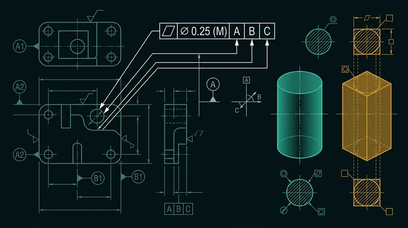
A datum is not a point marked on the part — it's a theoretically exact plane, axis, or point, established from a real, physical feature on the part (a face, a bore, a set of points) that inspection equipment can actually contact and measure from. When a drawing calls out datums A, B, and C in that order, it's defining a specific measurement sequence: A is contacted first (establishing a primary plane or axis), B second (removing another rotational degree of freedom), C third (removing the last one). Change the order and you change what the tolerance actually means — this is one of the most common real-world GD&T mistakes, and it's invisible unless you know to check the datum sequence.
MMC and LMC: the two modifiers everyone half-remembers
Two small circled letters change a lot:
- Ⓜ (MMC, Maximum Material Condition): the condition where a feature has the most material — the largest a shaft can be, or the smallest a hole can be. Calling out MMC on a position tolerance means you get bonus tolerance as the feature departs from MMC: a slightly undersized shaft (or oversized hole) is allowed to be positioned a bit further off from nominal, because there's more clearance to work with. This is genuinely useful — it can reduce rejected parts without loosening the functional requirement — but it only makes sense for features that mate with something else (a pin through a hole, a shaft in a bore).
- Ⓛ (LMC, Least Material Condition): the opposite — the least material a feature can have (smallest shaft, largest hole). LMC is used far less often, typically to guarantee a minimum wall thickness stays intact as a feature's location varies.
If a tolerance doesn't specify MMC or LMC, it applies RFS (Regardless of Feature Size) by default in the current standard — the tolerance is fixed regardless of the feature's actual size. Most engineers new to GD&T assume RFS is the "simple, safe default." It is safe, but it's also the option that gives up the bonus-tolerance benefit, so it's worth asking whether MMC actually applies before defaulting to RFS out of habit.
ASME Rule #1 vs ISO GPS (quick heads-up)
One systemic difference trips up global supply chains. Under ASME Y14.5, Rule #1 (the envelope principle) is the default: limits of size also limit form — a shaft at MMC must have essentially perfect form so it still fits the mating hole. Under the ISO GPS system, ISO 8015 makes the independency principle the default: size and form are independent unless you explicitly invoke the envelope requirement (circled Ⓔ) or other modifiers. Same drawing graphics can therefore mean different inspection criteria depending on which system the title block invokes — always state which standard governs the drawing.
When to use GD&T vs. when a plain ± tolerance is enough
This is the decision that actually matters day to day, and it's the one most guides skip:
Use a plain ± dimensional tolerance when:
- The feature doesn't mate with anything precisely (a mounting hole with generous clearance, an overall envelope dimension).
- There's a single, isolated dimension with no interaction between multiple features' locations.
- The part is low-volume and inspected manually with basic tools (calipers) rather than gauged/CMM'd — GD&T's advantages are largest when you're using functional gaging or CMM inspection that can actually exploit bonus tolerance and datum structure.
Use GD&T when:
- Multiple features need to align to each other or to a mating part (bolt patterns, bearing bores, a hole pattern that must match a mating flange).
- The part is round or cylindrical and orientation/runout genuinely affects function (shafts, rotating assemblies).
- You need to communicate "this is functionally critical, this is not" — a plain ±0.05 on every dimension tells the machinist nothing about priority; GD&T with tight position tolerance on the critical bolt pattern and loose profile tolerance elsewhere does.
- You're outsourcing manufacturing and inspection to a supplier you don't control closely — GD&T removes ambiguity that a plain tolerance leaves open to interpretation.
A worked example: two ways to dimension the same bracket
Imagine a bracket with two mounting holes that need to align with a mating part's studs.
Plain-tolerance approach: each hole gets an X and Y location dimension, each ±0.1 mm. This creates a square tolerance zone for each hole (0.2 mm × 0.2 mm), and the worst case falls on the diagonal — the corner-to-corner deviation is mm, roughly 41% larger than the 0.1 mm radius a designer usually has in mind, and the two holes' tolerances stack independently with no relationship to each other.
GD&T approach: a position tolerance of Ø0.2 mm at MMC, referenced to datums A (the mounting face) and B (one hole as the primary locating feature). This creates a round tolerance zone (matching how a round stud actually behaves in a round hole), correctly sized to the actual functional requirement, and gets bonus tolerance as the hole departs from its smallest allowed size — all of which the plain-tolerance version can't express.
Advanced tolerancing: the CLIC method and torsor theory
In complex mechanical designs, specifying GD&T callouts by "feel" or experience often leads to over-tolerancing, which raises manufacturing cost without a matching functional benefit. Academic tolerance-synthesis research addresses this with structured methods, notably CLIC (Cotation en Localisation avec Influence des Contacts — "location tolerancing with contact influence"), developed by Bernard Anselmetti's group at LURPA (ENS Cachan / Université Paris-Saclay) since the late 1990s.
CLIC models how parts position themselves through physical contacts between mating surfaces. It classifies contacts into primary (the main locating surface, which removes the most degrees of freedom), secondary, and tertiary contacts, and uses this to build a datum reference frame (DRF) systematically rather than by ad hoc designer choice.
To calculate the resulting 3D tolerance stack-up, CLIC uses the Small Displacement Torsor (SDT) representation, a standard tool in tolerance analysis. Each geometric deviation is modeled as a torsor combining small rotations ($\boldsymbol{\theta} = [\Delta\theta_x, \Delta\theta_y, \Delta\theta_z]^T\mathbf{d} = [\Delta x, \Delta y, \Delta z]^T$):
Using these displacement parameters, the method maps the virtual boundary conditions at Maximum Material Condition (MMC) for assemblability, and Least Material Condition (LMC) for mechanical clearance requirements — the same MMC/LMC concepts described above, applied systematically across an entire assembly rather than one feature at a time. This is a specialist technique used in tolerance-analysis software and academic tooling; most day-to-day drawing work doesn't need it, but it's worth knowing it exists once a design has enough interacting toleranced features that manual stack-up reasoning becomes unreliable. The specific numeric benefit of using CLIC on any given assembly (cost savings, yield) depends entirely on that assembly's geometry and can't be quoted as a general figure — treat any specific percentage claimed for a CLIC-optimized design as case-specific, not a rule of thumb.
Common mistakes worth avoiding
- Over-speccing everything with tight GD&T — this drives up inspection cost without improving function. Reserve tight callouts for features that are actually functionally critical.
- Getting the datum order wrong or inconsistent across related drawings, so a part passes inspection against one datum reference frame but doesn't actually fit the mating part measured against a different one.
- Using position tolerance without a clear mating feature in mind — position only makes sense relative to how the part will actually be assembled or measured.
- Assuming GD&T replaces size tolerance — it doesn't. A hole still needs a diameter tolerance; position tolerance controls where that hole is, not how big.
The bottom line
GD&T earns its complexity when features need to align with something else, when a part is outsourced without close oversight, or when function genuinely depends on orientation and location rather than raw size. For everything else, a well-chosen plain tolerance is simpler to read, cheaper to inspect, and just as functionally correct. The skill isn't memorizing all 14 symbols — it's knowing which of the two approaches actually matches what the part needs to do.
Sources: ASME Y14.5-2018 — Dimensioning and Tolerancing · ISO 8015:2011 — GPS fundamentals (independency principle) · GD&T Basics — ISO GPS vs ASME Y14.5 · MakerStage — GD&T Symbols Chart · Fictiv — GD&T 101 · Formlabs — GD&T Basics.
Frequently asked questions
- Does ASME Y14.5 or ISO GPS apply by default on a drawing?
- Neither applies automatically — the title block or a general note must invoke one explicitly, because the two systems disagree on the default relationship between size and form (Rule #1 vs. the independency principle).
- What is the difference between MMC and RFS in GD&T?
- MMC (Maximum Material Condition) grants bonus position tolerance as a feature departs from its tightest size limit; RFS (Regardless of Feature Size) is the default when no modifier is shown, and keeps the tolerance fixed regardless of the feature's actual produced size.
- Why does the order of datums A, B, C matter on a drawing?
- Each datum removes a specific set of degrees of freedom in sequence during inspection — changing the order changes which surface is contacted first, which changes the measured result even though the drawing graphics look the same.
- Is the CLIC tolerancing method something a typical machine shop needs?
- No — CLIC is an academic/software-level method for synthesizing tolerances across many interacting features in a complex assembly; most individual drawings are specified correctly with the standard GD&T symbols and a well-chosen datum reference frame alone.