Hertzian Contact Stress Calculations in Mechanical Design: Spheres, Cylinders, and Gear Teeth
How to calculate peak contact pressure and sub-surface shear stresses for point and line contact, with engineering limits for bearings and mating gear teeth.
When two curved surfaces are pressed against each other under a load, the theoretical contact area is zero: a point for two spheres, or a line for two cylinders. In reality, material elasticity causes the contact region to deform into a small finite area—a circle or a rectangle.
This localized contact deformation generates extremely high pressures, known as Hertzian Contact Stress (named after Heinrich Hertz, who solved this in 1881). Unlike standard bending or tensile stresses, Hertzian contact stresses behave non-linearly, and their failure modes occur beneath the surface, making them a common source of pitting and spalling in bearings, gears, and cams.
Spheres on Flat Surfaces: Point Contact
A classic example of point contact is a ball bearing rolling in a raceway. When a force ($F$) presses a sphere of radius $R$ onto a flat surface, the contact area is a circle of radius $a$:
$$a = \left( \frac{3 F R_{eq}}{4 E^*} \right)^{1/3}$$
Where:
- $R_{eq}$ is the equivalent radius of curvature ($R_{eq} = R$ when contacting a flat plate).
- $E^$ is the equivalent elastic modulus, calculated from the Young's Modulus ($E$) and Poisson's Ratio ($\nu$) of both materials: $$\frac{1}{E^} = \frac{1 - \nu_1^2}{E_1} + \frac{1 - \nu_2^2}{E_2}$$
The contact pressure is distributed parabolically across the circular area, peaking at the center. The maximum contact pressure ($p_{max}$) is:
$$p_{max} = \frac{3 F}{2 \pi a^2}$$
Notice that because $a \propto F^{1/3}$, the peak pressure is proportional to the cube root of the load: $p_{max} \propto F^{1/3}$. Doubling the load does not double the contact stress; it only increases it by roughly $26%$.
Cylinders on Flat Surfaces: Line Contact
For line contacts, such as a cylindrical roller bearing or mating gear teeth, the contact region deforms into a rectangle of half-width $b$ and length $L$:
$$b = \left( \frac{4 F R_{eq}}{\pi L E^*} \right)^{1/2}$$
The maximum contact pressure ($p_{max}$) occurs along the center axis of the rectangular contact band:
$$p_{max} = \frac{2 F}{\pi b L}$$
For line contact, because $b \propto F^{1/2}$, the peak pressure is proportional to the square root of the force: $p_{max} \propto F^{1/2}$.
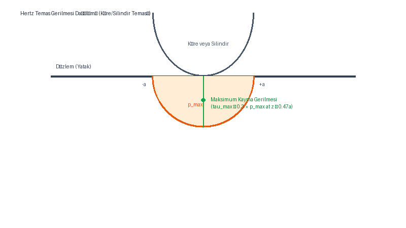
Why Contact Failures Start Beneath the Surface
If you section a failed bearing or gear tooth, you will often find craters (pitting or spalling) where metal flaked away. It is tempting to assume the failure started on the surface due to high pressure. However, elastic stress field analysis shows that the critical shear stress ($\tau$), which causes plastic deformation and micro-cracking, peaks below the surface.
For point contact, the maximum shear stress ($\tau_{max}$) occurs along the vertical axis at a depth of:
$$z \approx 0.47 a$$
At this depth, the shear stress reaches:
$$\tau_{max} \approx 0.31 p_{max}$$
Because the metal is repeatedly stressed and unstressed as a ball or roller rolls over it, fatigue cracks initiate at this sub-surface depth, propagate outward, and eventually cause the surface material to flake off. This is why surface hardening treatments (like carburizing or nitriding) must penetrate deep enough to cover the depth of maximum shear stress ($z$), rather than just coating the outer skin.
Engineering Limits and Application
Hertzian contact stresses frequently exceed $1000\ \text{MPa}$ in industrial machinery. While steel would yield at much lower limits under tension, it can survive much higher stresses under localized, triaxial compressive contact.
Typical design limits for $p_{max}$:
- Through-hardened bearing steel (e.g., 52100 / 100Cr6 at 60 HRC): $1500 - 2000\ \text{MPa}$ under static load.
- Carburized gear teeth (case-hardened): $1000 - 1400\ \text{MPa}$ depending on lubrication and cycle life requirements.
- Soft steel / structural joints: $300 - 500\ \text{MPa}$ to prevent localized indentation.
Conclusion
Hertzian contact stress is a non-linear phenomenon where the highest threat to the joint exists invisible, beneath the surface. When designing rolling elements, gear meshes, or cam followers, calculating $p_{max}$ and its associated sub-surface depth $z$ is the only way to select the appropriate surface heat treatment depth and prevent catastrophic fatigue pitting.
Sources:
- Hertz, H. (1881). Ueber die Berührung fester elastischer Körper (On the contact of elastic solids). Journal für die reine und angewandte Mathematik.
- Johnson, K. L. (1985). Contact Mechanics. Cambridge University Press.