Is Text-to-CAD Accurate Enough for Manufacturing?
It depends on the part and the tool. How to tell whether a text-to-CAD file is manufacturable — and what separates a demo from a usable STEP.
- Author:
- Cadagen
- Technical review:
- CADAGEN Engineering Team · Mechanical Engineer
- Last updated:
- August 16, 2026
- Sources:
- 3 primary references, listed below
Short answer: it depends entirely on the part and the tool — and the gap between "looks right" and "can be made" is where most text-to-CAD tools quietly fail. For standard mechanical parts with clear requirements, accuracy can be excellent. For novel geometry, or when a tool ignores manufacturing constraints, the file can look perfect on screen and fall apart on the shop floor.
This article is about how to tell the difference before you cut metal.
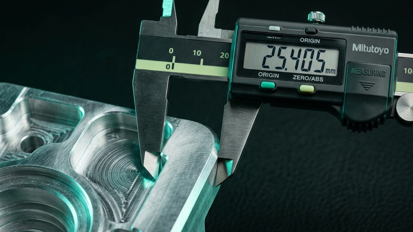
The accuracy problem nobody demos
The category has a known weak spot. Many AI-generated CAD parts look impressive in a demo but fall apart the moment you try to add tolerances, run stress analysis, or send them to manufacturing — they're often not parametric, carry no design history, and have no awareness of manufacturing constraints.
So "accurate" can't just mean "the picture matches your words." For manufacturing, it has to mean dimensionally correct, properly toleranced, and actually producible.
What "manufacturable" really means
Three things have to be true before a CAD file is ready to make:
- Dimensional correctness. The sizes match intent — and where it matters, they reference real standards (an M10 thread is an M10 thread, not "about 10 mm").
- Tolerances and fits. A hole that takes a bearing isn't "20 mm." It's 20 mm with a fit. A tool that can't express that isn't giving you a manufacturing file.
- Design for Manufacturing (DFM). Wall thicknesses, draft angles, internal radii, and feature sizes have to suit the process — machining, casting, sheet metal, or printing.
Why standard parts are a hidden accuracy lever
Here's something the flashy demos miss: the most reliable way to be accurate is to not reinvent a standard part. A bolt, a gear, a bearing seat — these are defined by standards (ISO, DIN). A tool that pulls from real standard-part definitions will be far more accurate than one improvising the geometry.
This is also why "dimensionally correct" and "dimensioned in the file" are not automatically the same thing. Because a text-to-CAD pipeline builds geometry from a generation script executed by a CAD kernel rather than freehand drawing, a stated 25 mm bore really is built at 25.000 mm — there is no equivalent of a hand slipping on a sketch. But the kernel only knows what the script tells it. If the script hard-codes a wall thickness the prompt never specified, that value is just as precise and just as unreviewed as one you did specify — precision is not the same thing as correctness, and a tool that presents assumed dimensions with the same confidence as stated ones is hiding exactly the information you need to know what to check first.
When should you trust automation — and when ask a human?
Short rule: automate standard, well-specified parts; escalate novel, ambiguous, or safety-critical work. The part-class decision framework is in when to trust automation vs. ask an expert — this article stays on how to judge accuracy of a given file.
Why one accuracy number is always misleading
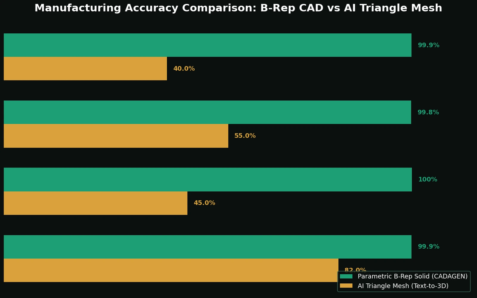
Vendors like round, confident numbers — "95% accurate." The number rarely specifies accurate at what: visual resemblance, dimensional correctness, or manufacturability are three different bars, and a part can pass the first and fail the other two. Worse, a single blended number usually hides a real split: a tool can be extremely reliable on standard, catalog-backed parts (fasteners, bearings, gears) and much less reliable on freeform custom geometry, because these are genuinely different problems — one is a lookup/matching task, the other is open-ended generation. Reporting one number across both hides exactly the information you need to decide whether a given tool is safe to use for your specific part.
A concrete example of "looks right, isn't right"
A shaft and the bore it's meant to spin inside can both be labeled "10mm" and look correct in a 3D viewer. Apply real manufacturing tolerances, though, and two independent "10mm" dimensions can produce either a bore so tight the shaft won't turn, or so loose the fit is unusably sloppy — neither of which is visible until real tolerances (a matched fit like H7/g6) are actually specified. See tolerances in CAD: what AI tools usually get wrong for the mechanics of why this specific failure is so common and so invisible on screen.
What an independent test actually found
Xometry Pro ran the same three functional prompts — a simple cylinder, a 24-tooth involute gear with stated module and pressure angle, and a 15-branch manifold block — through seven text-to-CAD tools in 2026. The split was stark: five of the seven (Zoo, AdamCAD, CADGPT, Vondy, CADScribe) attempted CAD-ready output in formats like STEP, STL, or DXF; the other two returned 2D illustrations, not solids, and were unusable for manufacturing regardless of how good the image looked. Among the five CAD-producing tools, simple parametric shapes came out usable across the board, but the high-complexity manifold prompt — multiple branching channels, fillets, and mounting holes on one body — separated the tools clearly, with several producing geometry that either failed to resolve cleanly or dropped features the prompt asked for. The pattern matches what this article argues from first principles: reliability drops as geometric complexity rises, and a tool's behavior on a simple cylinder tells you very little about its behavior on a 15-branch manifold.
A checklist: evaluating a text-to-CAD tool's accuracy
Before you rely on any tool, ask:
- Does it output editable STEP (B-Rep), not just a mesh?
- Can you specify and see tolerances and fits?
- Does it reference real standards for fasteners, gears, and bearings?
- Is there a sanity check on manufacturability for your process?
- When it can't do the part well, does it tell you — or quietly hand you a broken file?
- Is there a fallback to a human for the hard cases?
A quick FAQ
Does "STEP output" alone mean a tool is accurate? No — STEP just means the file format is capable of exact geometry. A tool can export STEP with dimensionally wrong or untoleranced geometry just as easily as with correct geometry; the format guarantees editability, not correctness.
Should I trust a tool more because it lets me chat and refine the result? Iterative refinement helps you converge on the right shape, but it doesn't replace checking the final dimensions against your actual spec — a conversation can converge on something that looks right to both parties and still miss a functional requirement neither side thought to mention.
The bottom line
Text-to-CAD can be accurate enough for manufacturing — for the right parts, with a tool that takes tolerances, standards, and manufacturability seriously and is honest about its limits. Treat "it looks right" as the beginning of verification, not the end.
Sources: ISO 286 — Limits and fits · ASME Y14.5-2018 · Xometry Pro — We Tested 7 Text-to-CAD Tools.
Frequently asked questions
- Is text-to-CAD accurate enough for manufacturing?
- For standard prismatic parts described with real dimensions, the geometry can be dimensionally exact — the kernel builds it from numbers, so a stated 25 mm bore is 25.000 mm. Accuracy fails elsewhere: dimensions you did not state were assumed, tolerances are usually absent, and manufacturability is not guaranteed unless the tool checks it. Treat the file as a first draft requiring review, not a released deliverable.
- How do I check whether a generated CAD file is correct?
- Check the interfaces first, because that is where errors cost the most: bore diameters, bolt patterns, mating faces and overall envelope, measured in your own CAD rather than by eye. Then check manufacturability — minimum wall thickness, internal corner radii, tool access, draft — and finally check which dimensions were assumed rather than specified.
- Why does the same prompt give different results?
- Language models are sampled rather than evaluated, so two runs can produce slightly different generation scripts. Dimensions you explicitly stated will match on both; dimensions the system had to assume may differ. This is why a tool that reports which values were assumed is more trustworthy than one that presents everything identically.