What Is Text-to-CAD? A Practical Guide
Text-to-CAD turns a written part description into an editable STEP solid. How it works, what it does well, and why manufacturing sign-off stays with you.
- Author:
- Cadagen
- Technical review:
- CADAGEN Engineering Team · Mechanical Engineer
- Last updated:
- August 16, 2026
- Sources:
- 3 primary references, listed below
Text-to-CAD is a class of tools that turn a written (or visual) description of a part into an editable CAD file — most usefully a STEP file you can open in SolidWorks, Fusion, Inventor, or CATIA. Instead of modeling a part feature by feature, you describe it ("an M10 hex bolt, 40 mm long, ISO metric thread") and the tool returns geometry you can inspect, edit, and send to manufacturing.
This guide explains, in plain terms, how text-to-CAD works, what it's genuinely good at in 2026, and the limits every engineer should know before relying on it.

How does text-to-CAD work?
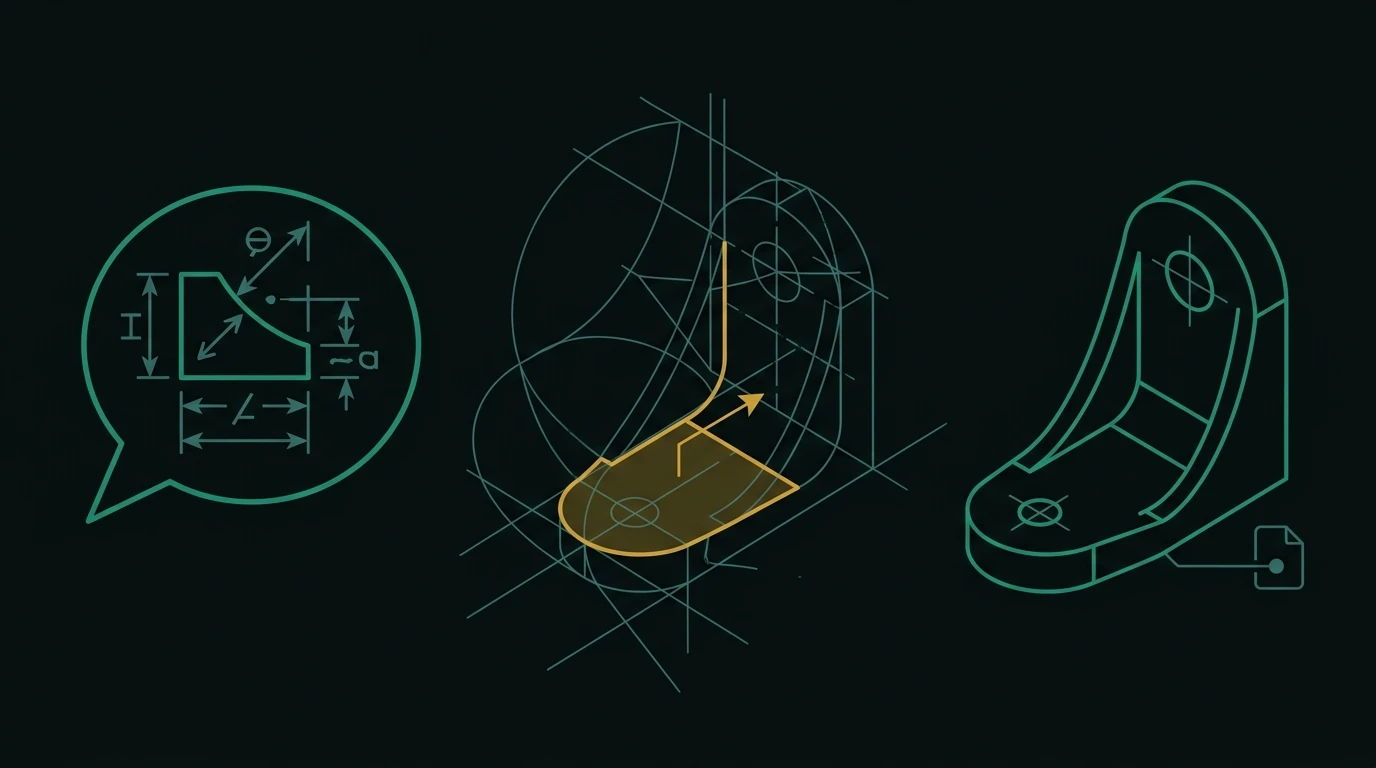
At a high level, three things happen between your prompt and your file:
- Interpretation. The tool reads your description — and, in some tools, a photo or sketch — and works out the geometric intent: shapes, dimensions, features, and standards you referenced.
- Geometry generation. It produces a precise 3D solid model from that intent. The important word is solid: good tools generate B-Rep (boundary-representation) geometry, the same kind native CAD uses — not a triangle mesh.
- Export. It writes out a standard CAD file. STEP (ISO 10303) is the one that matters for engineering, because it's editable and accepted by every major CAD package.
You don't need to know the internals to use it well — but you do need to know what kind of output you're getting, because that determines whether you can actually work with it.
One implementation detail is worth understanding, because it explains most of the behaviour you will observe: in practice the model does not draw the geometry. It writes a generation script — a program in a CAD scripting API — and a geometry kernel executes that script to build the solid. That indirection is why output is exact rather than approximate, why it can expose adjustable parameters, and why failures tend to be all-or-nothing rather than subtly wrong-looking. The mechanics are set out in how LLMs generate CAD, and the scripting layer itself in code CAD explained.
Why "editable geometry" is the whole point
Many "AI 3D" tools generate a mesh (a shell of triangles), which is fine for rendering or some 3D printing, but painful for engineering: you can't cleanly change a dimension, add a fillet, or apply a tolerance. Text-to-CAD tools that output B-Rep / STEP give you a model you can edit like any other CAD part.
| Text-to-CAD (B-Rep / STEP) | Text-to-3D (mesh / STL) | |
|---|---|---|
| Editable in CAD | Yes — faces, edges, features | Not really — just triangles |
| Dimensions/tolerances | Can be applied | Hard or impossible |
| Best for | Engineering, manufacturing | Rendering, some 3D printing |
| File you want | STEP | STL/OBJ |
What can text-to-CAD do well today?
- Standard, well-defined mechanical parts: brackets, flanges, plates, spacers, standard fasteners, gears, and bearings — especially when you reference a standard (ISO, DIN).
- Speed on the boring 80%: the routine parts that eat drafting time.
- Starting points: a correct base model you refine, instead of a blank sketch.
Where does it still fall short?
Be honest with yourself about the limits — this is where most disappointment comes from:
- Highly novel or organic geometry is hit-or-miss.
- Implicit intent ("make it strong") isn't engineering input; tolerances, loads, and fits have to be stated.
- Manufacturability isn't guaranteed by every tool — some produce shapes that look right but can't be made with your process.
- Assemblies degrade with component count. Reasoning about mates, clearances and stack-ups across many parts at once is where these systems are weakest; single parts and two- or three-component assemblies work far better than large ones.
- Tolerances default to nominal. Unless you say a diameter is a bearing seat, it will be modelled as a plain dimension with no fit — see tolerances AI tools get wrong.
- Non-determinism is real. The same description can produce slightly different geometry twice. Dimensions you stated will match; ones you left out may not.
The full, specific account of the limits — and what to do about each one — is in the real limitations of AI CAD.
How to tell a usable tool from a demo
Four questions separate them, and none of them are about the render:
- What is the export format? STEP means editable solid geometry. STL or GLB alone means a mesh — see text-to-CAD vs text-to-3D.
- What is checked before delivery? "The model is good" is not an answer. A closed solid, non-zero volume, an envelope matching the request and minimum wall thickness are answers.
- Which dimensions can you change afterwards? A model with exposed driving parameters is editable; one with a single uniform scale factor is a picture with a file extension. See parametric CAD.
- Does it distinguish given from assumed dimensions? If everything is presented with equal confidence, you have to re-verify everything.
A category-level survey against these criteria is in best text-to-CAD tools.
What actually happens with standard components
"M10 bolt" shouldn't invent a plausible shape — it should match real catalog geometry. That's a lookup problem, not a design problem, and it's why standard-part reliability and custom-geometry reliability are different questions. Details: generating fasteners, gears & bearings correctly.
A realistic example, start to finish
A specific prompt ("L-bracket, 60×40×5 mm, two M6 clearance holes, NEMA 17 mount") gives the three pipeline steps real constraints; "a motor bracket" forces guessing. How to write that kind of prompt — and what "strong" vs. "weak" looks like — is covered in natural language to CAD, with a full prompt structure and before/after examples in how to write a CAD prompt.
A realistic loop looks like this:
- Describe the part with envelope, datum, features-with-positions, process and material.
- Inspect the preview — check the interfaces first: bores, bolt patterns, mating faces.
- Measure the dimensions that matter in your own CAD, not by eye.
- Adjust one parameter at a time rather than rewriting the whole description.
- Export STEP for the shop, plus a mesh only if something is being printed — see CAD file formats explained.
- Review against a manufacturability checklist before it leaves the building: DFM 101.
Who is text-to-CAD for?
Hardware startups and product teams moving fast, job shops and fabricators turning descriptions into quotable geometry, and engineers who'd rather spend their time on the hard 20% than re-drawing the routine 80%. It's a weaker fit for anyone who needs the tool to make engineering judgment calls on their behalf — novel mechanisms, safety-critical structures, or genuinely ambiguous requirements still need a person in the loop; see when to trust automation vs. ask an expert for where that line sits in practice.
The bottom line
Text-to-CAD in 2026 is real and useful — if you treat it as a fast, capable drafter for standard parts and you check the output like you'd check any drafter's work. Want to see it on your own part? Try a prompt in the design studio.
Frequently asked questions
- What is text-to-CAD?
- Text-to-CAD is a class of tools that turn a written or visual description of a mechanical part into an editable CAD file, usually STEP. Instead of modelling feature by feature, you describe the part with real dimensions and the tool returns solid geometry you can open in SolidWorks, Fusion, Inventor or CATIA, inspect, edit and send to manufacturing.
- How is text-to-CAD different from AI 3D model generators?
- Text-to-CAD targets editable boundary-representation solids for engineering; text-to-3D generators produce triangle meshes for rendering, games and general 3D printing. A mesh has no exact dimensions, so you cannot cleanly change a diameter, apply a tolerance or machine a smooth surface from it. The practical test is the export format: STEP means solid geometry, STL or OBJ means mesh.
- Is text-to-CAD accurate enough for manufacturing?
- It depends on the part and the tool. For standard prismatic parts described with real dimensions, the geometry can be dimensionally exact. It is not a substitute for review: generated models routinely carry nominal dimensions with no tolerances, and any dimension you did not state was assumed. Treat the output as a first draft that needs the same check you would give a junior drafter's work.
- Can text-to-CAD replace a CAD engineer?
- No. It removes drafting time on routine geometry, which is real. It does not select load cases, choose safety factors, pick a manufacturing route, specify a GD&T scheme, or take responsibility for a released design. Those remain engineering decisions with professional accountability attached.