DFM 101: Designing Parts That Can Actually Be Made
Design for manufacturing basics for engineers using text-to-CAD — wall thickness, internal radii, hole sizing, draft angles, and how to prompt with the target process in mind.
- Author:
- Cadagen
- Technical review:
- CADAGEN Engineering Team · Mechanical Engineer
- Last updated:
- August 16, 2026
- Sources:
- 3 primary references, listed below
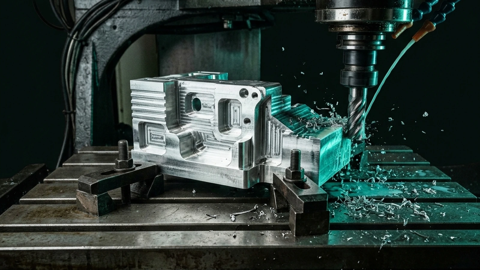
Design for manufacturing (DFM) means shaping a part so a real process — machining, sheet metal, injection molding, 3D printing — can produce it reliably, cheaply, and consistently, instead of designing an idealized shape and hoping the process can somehow cope. A part can be a perfectly valid, closed solid and still fail DFM entirely — validity and manufacturability are two separate checks, and conflating them is one of the most common mistakes in evaluating any generated CAD model.
Why DFM has to be process-specific
There's no single universal rule for "makeable" — a wall thickness that's perfectly fine for CNC machining might be far too thin for injection molding, and a sharp internal corner that's trivial to 3D print is physically impossible to mill with a round cutting tool. This is the core reason DFM can't be a single checklist; it has to reference the actual process a part is headed for.
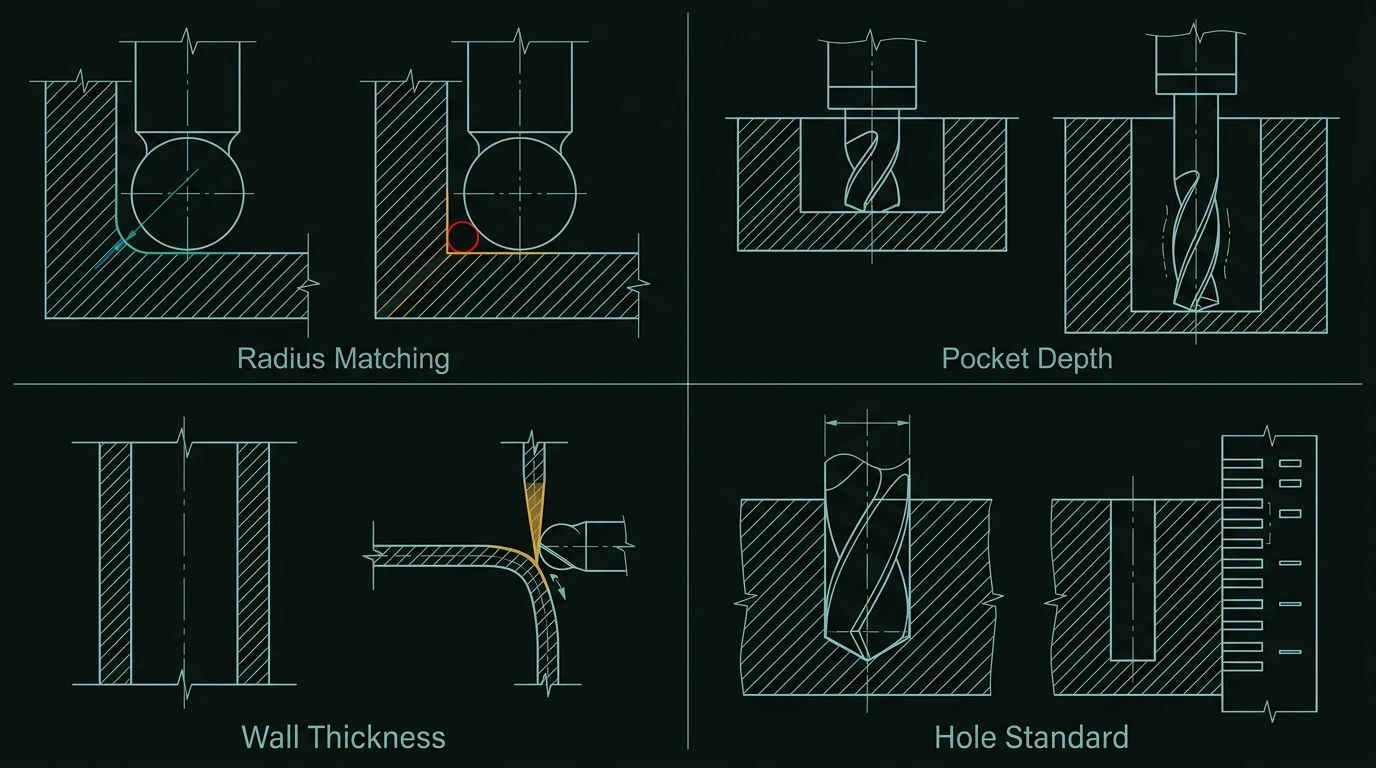
Quick rules that save rework, by process
| Topic | CNC machining | Injection molding | 3D printing (FDM) |
|---|---|---|---|
| Internal corners | Avoid zero-radius corners — tool radius always leaves a fillet; prefer of pocket depth when possible | Radiused corners reduce stress concentration and improve flow | Sharp corners are fine, but thin unsupported overhangs are not |
| Wall thickness | Keep metals roughly recommended (shops often flag as fragile); plastics thicker | Must stay within a narrow, consistent range or the part warps/sinks | Under the printer's minimum reliable thickness, walls fail to print solidly |
| Vertical features | No draft needed | Draft angle required (typically 1–2°) so the part releases from the mold | No draft needed, but overhangs beyond ~45° need support |
| Holes | Standard drill sizes beat "magic" diameters — matches real tooling; drilled depth diameter is the usual sweet spot | Small deep holes are hard to mold cleanly; consider core pins | Small holes may shrink slightly and need clearance allowance |
| Tolerances | Tighten only where function requires it — tight tolerance = higher cost | Molded tolerance is inherently looser than machined; don't over-specify | Layer-based processes have lower inherent precision than machining |
These CNC numbers are shop heuristics consistent with common DFM checklists (e.g. Protolabs machining toolkit, MakerStage CNC guidelines) — always confirm against your supplier's capability sheet.
Text-to-CAD + DFM: say the process, not just the shape
When you write a description for generation, name the actual manufacturing process — "3mm aluminum plate, laser cut and bent" is a fundamentally different design problem than "machined from solid block," even if the finished shape looks similar in a render. Naming the process steers feature choices (bend reliefs vs. machined fillets, sheet-metal-appropriate hole spacing vs. solid-stock pocketing) even when the generation process isn't perfect — it narrows the space of reasonable interpretations dramatically.
The specific mistakes that cost the most rework
- Zero-radius internal corners on a machined part. A rotating cutting tool is physically round; it cannot produce a sharp internal corner. If your design intent needs one (for a mating flush surface), the actual part won't match unless you plan for the tool radius or use a different process (EDM, for instance).
- Uniform wall thickness assumptions carried over from a different process. A wall thickness that's standard for injection molding is often unnecessarily thick — and expensive — for the same part machined from solid stock, and vice versa: a thin machined wall that's fine structurally may be too thin to reliably fill in a mold.
- No draft on vertical walls for molded or cast parts. Without draft, the part drags against the tool on ejection, damaging the surface finish or seizing entirely. This is invisible in a static 3D model and only shows up once someone tries to actually mold the part.
- Ignoring minimum feature size for the chosen process. A 3D printer, a mill, and a mold each have a different practical floor on how small a feature (a hole, a rib, a boss) can be and still come out reliably.
Verify before you cut metal
- Open the STEP file in your actual CAD tool, not just a lightweight viewer — check that features are clean and the file is a proper solid.
- Check mass properties — an unexpectedly high or low mass/volume can flag an accidental scaling error or a hidden internal void.
- Section a suspect area — cutting a cross-section through a thin wall or an internal feature often reveals a manufacturability problem that's invisible from the outside.
- Ask the honest question: "would I sign this drawing?" If the answer is "probably, but I haven't actually checked X," that's the signal to check X before committing to a cutting or molding run.
DFM Physics and Engineering Formulas
To evaluate manufacturability limits beyond basic geometric guidelines, designers apply physical and structural formulas for each specific process:
1. CNC Milling Tool Deflection Formula
When milling a deep pocket or slot, the lateral cutting forces () cause the tool to deflect, resulting in dimensional inaccuracies and surface finish defects. The tool deflection () can be modeled using cantilever beam theory:
Where the area moment of inertia () for a round solid tool of diameter is:
Thus, tool deflection is highly sensitive to the tool length-to-diameter ratio:
DFM Rule: Machine shops commonly cap tool overhang at roughly for rigidity — this is the same order of magnitude as the hole-depth-to-diameter guideline above, and the reason is the same cubic sensitivity to length shown by the deflection formula. Treat it as a starting point to discuss with your shop, not a fixed pass/fail number — actual deflection depends on the specific tool, material and cutting parameters, so ask for your supplier's guidance on deeper features rather than relying on a single threshold.
2. Injection Molding Wall Thickness and Draft
In injection molding, varying wall thicknesses lead to differential cooling rates, resulting in sink marks and warping. Ribs are added for stiffness, but their thickness () is commonly kept around 60% of the nominal wall thickness () or less:
Additionally, to ensure the part can be ejected from the mold cavity, vertical walls require draft angles. The one-sided dimensional offset () produced by a draft angle over a wall depth follows directly from the taper geometry:
For example, 1° of draft over a 50 mm-deep wall produces roughly 0.87 mm of offset per side — small on paper, but enough to matter on a mating surface, which is why draft has to be accounted for in the nominal dimension, not treated as a free addition.
Case Study: Before vs. After CAD Optimization
A mechanical engineer used an AI-generative CAD tool to design a mounting bracket for a camera module intended to be injection-molded from ABS plastic.
- Before Optimization: The initial generated bracket features sharp internal corners, thin 1.0 mm walls running next to heavy 4.0 mm solid bosses, and absolute vertical flanges without draft. While the STEP file is a valid watertight solid, molding this design would result in severe sink marks on the aesthetic faces, incomplete filling (short shots) near the thin walls, and part tearing upon ejection from the mold.
- After DFM Application:
- Fillets Added: Internal corners are filleted to mm (distributing stress and facilitating plastic flow).
- Wall Uniformity: The nominal wall thickness is set to a uniform 2.0 mm. Heavy bosses are cored out so that they match the nominal wall thickness.
- Rib Thickness Adjusted: Structural reinforcement ribs are reduced to mm ( of ).
- Draft Applied: A draft angle is added to all vertical flanges.
- Result: Mold flow simulation indicates a fill rate, a reduction of sink mark depth from 0.25 mm to less than 0.03 mm (within tolerance), and successful ejection without cosmetic damage. Production tool costs were reduced because no complex slides or EDM post-processing were needed.
The bottom line
DFM is not optional polish layered on top of a "real" design — it's the difference between a pretty render and a part that actually ships. The check is inherently process-specific: naming the manufacturing process at generation time, and verifying wall thickness, draft, internal radii, and feature size against that specific process's real limits, is what turns a valid solid into a manufacturable one.
Related reading: Why most AI-generated CAD fails on the shop floor · Standard parts vs. custom geometry cost · Draft views: what they are not
Sources: Protolabs — Design for machining toolkit · MakerStage — CNC design guidelines · Rapid Manufacturing — DFM guide for CNC.
Frequently asked questions
- What is design for manufacturing (DFM)?
- DFM is the practice of shaping a part so that a real process can actually produce it economically — respecting minimum wall thickness, internal corner radii a cutter can reach, draft angles for moulding and casting, tool access, and standard hole and thread sizes. A model can be geometrically valid and still be impossible or expensive to make.
- Why do DFM rules differ between processes?
- Because the constraints come from the physics of each process. Machining is limited by tool geometry and access, so internal corners cannot be sharper than the cutter radius. Injection moulding is limited by flow, cooling and ejection, so uniform walls and draft angles matter. Additive is limited by overhang angle and support removal. The same shape can be trivial in one process and unmakeable in another.
- How do I apply DFM to an AI-generated model?
- Name the manufacturing process and material in the request, because that determines which rule set applies. Then check the generated model against the specific numbers for that process: minimum wall, internal radii, draft, hole sizes against a standard drill list, and whether a tool can physically reach every surface.