Capabilities
Measure and draft views
A 3D preview without a ruler or a printable envelope leaves you guessing in the browser.
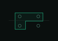
30-second flow
Open Measure for two points or a cylinder face → or create draft views (one solid or a combined assembly silhouette) → download SVG/DXF as a draft.
What it does
- Measure two-point distance and cylinder-face diameter on the current preview.
- Build combined front, top, side and isometric draft views; multi-body models are supported.
- Label the result as a draft, not a manufacturing drawing.
What it does not
- Call a two-point span a diameter.
- Produce GD&T or part balloons; the sheet is a draft, not a manufacturing release.
- Open a sheet above 96 bodies — download STEP for that assembly.
Example
A bracket or a table assembly can show a combined draft; a crowded assembly tells you to download STEP.
ISO & DIN SPECIFICATION
Verified Engineering Standards Reference
Standard dimensional references you can consult while describing a part: fits, keys, and metric threads.
| Nominal Size Range (mm) | Hole H7 (µm) | Shaft g6 (Sliding, µm) | Shaft h6 (Locational, µm) | Shaft k6 (Transition, µm) | Shaft p6 (Press Fit, µm) |
|---|---|---|---|---|---|
| >3 – 6 mm | +12 / 0 | −4 / −12 | 0 / −8 | +9 / +1 | +20 / +12 |
| >6 – 10 mm | +15 / 0 | −5 / −14 | 0 / −9 | +10 / +1 | +24 / +15 |
| >10 – 18 mm | +18 / 0 | −6 / −17 | 0 / −11 | +12 / +1 | +29 / +18 |
| >18 – 30 mm | +21 / 0 | −7 / −20 | 0 / −13 | +15 / +2 | +35 / +22 |
| >30 – 50 mm | +25 / 0 | −9 / −25 | 0 / −16 | +18 / +2 | +42 / +26 |
Values verified against official standards: ISO 286-2:2010, DIN 6885-1:2021-11, and ISO 261:1998 / ISO 965-1:2013.