Natural Language to CAD: From Prompt to Part
How plain-language mechanical descriptions become editable CAD solids, exactly what to include so the first draft is usable, and where a human still needs to step in.
- Author:
- Cadagen
- Technical review:
- CADAGEN Engineering Team · Mechanical Engineer
- Last updated:
- August 16, 2026
- Sources:
- Links and standards referenced in the article
Natural language to CAD means describing a part in everyday words and receiving an editable solid model in return — usually exported as STEP for downstream engineering and manufacturing workflows. The core idea sounds simple, but the gap between a vague description and a usable result is entirely a function of how much real information the description actually contains.
What a description is really doing
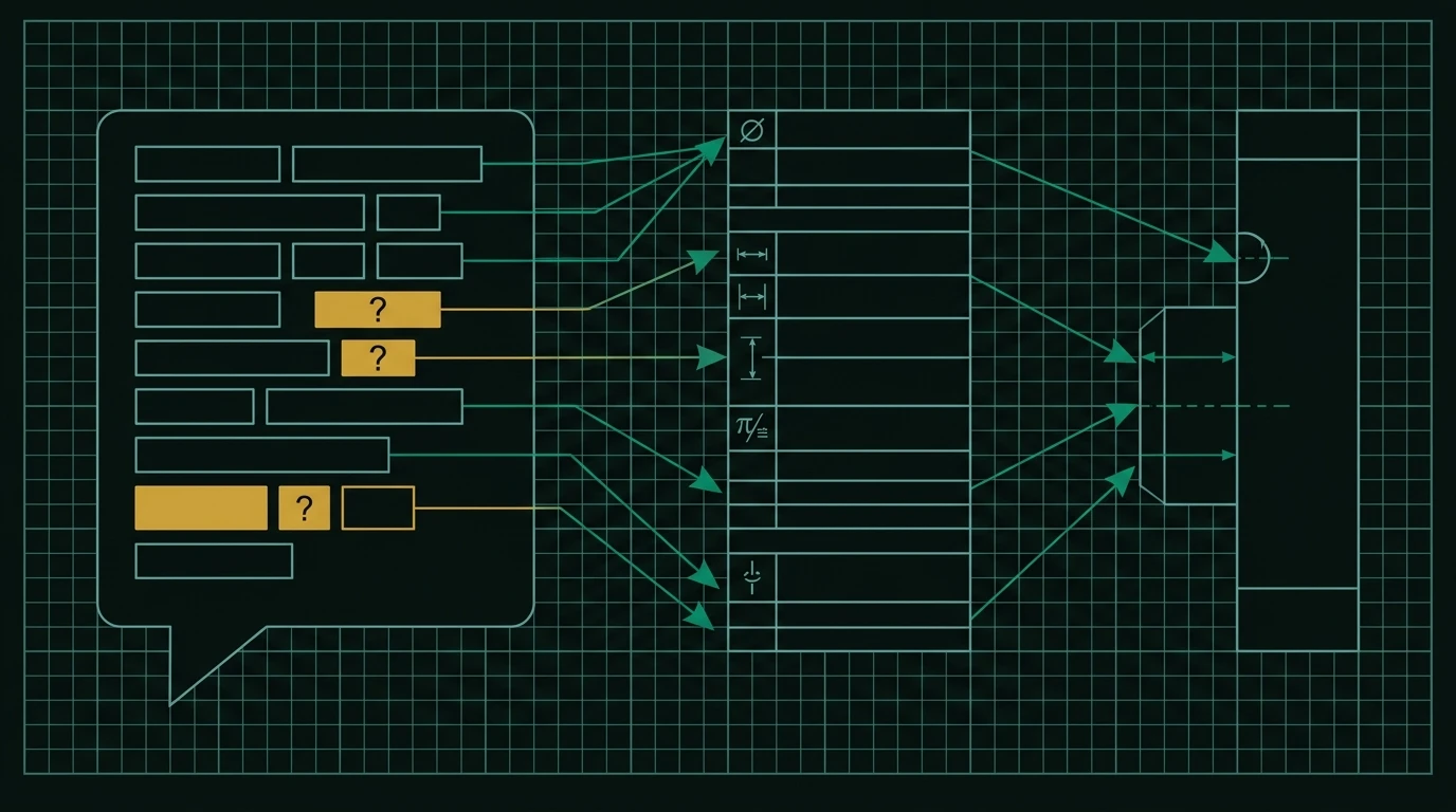
A natural-language prompt isn't magic input to a black box — it's a set of constraints that either fully determine the part (leaving nothing to guess) or leave gaps that have to be filled somehow, either by a reasonable default, an explicit clarifying question, or — worst case — a silent assumption that may not match what you meant. Understanding this reframes the whole exercise: writing a good prompt is really about minimizing the number of gaps left for the system to fill.
What to include in a good prompt
- Overall shape (plate, bracket, cylinder, gear, housing) — this anchors the basic topology before any detail is added.
- Critical dimensions with units (mm unless you state otherwise) — every dimension that matters for function or fit should be a number, not a qualitative word like "small" or "thick."
- Standards when relevant (M10 bolt, ISO gear module, DIN flange) — naming a real standard lets the system pull exact, catalog-correct geometry instead of approximating a shape from scratch. See ISO metric thread sizes explained for how much information a standard designation like "M10x1.5" actually encodes.
- Manufacturing context (sheet metal vs. machined block, injection molded vs. 3D printed) when it changes the design — a part that will be bent from sheet metal has different constraints (bend radius, relief cuts) than the same shape machined from solid stock.
- Reference points and relationships — "10mm from the left edge," "centered on the bolt pattern" — gives the system a concrete anchor rather than an ambiguous "somewhere near there."
A concrete before/after
Weak prompt: "A motor bracket."
Strong prompt: "An L-shaped bracket, 60mm x 40mm x 5mm thick, with two M6 clearance holes 10mm from each end on the long side, for mounting a NEMA 17 stepper motor."
The difference isn't stylistic — the strong version gives the generation process real constraints to satisfy: exact overall dimensions, exact hole size and placement, and a named standard (NEMA 17) that implies a specific bolt pattern the system can look up rather than guess.
Why standard designations do more work than any other sentence
Of everything you can put in a prompt, naming a real standard removes the most ambiguity per word. "M8x1.25 bolt" fixes the nominal diameter, the thread pitch, and — combined with a head style like ISO 4762 — the head geometry, all from three characters plus a number. "An 8mm bolt" leaves the pitch, head shape, and length unstated, each of which the system now has to assume. The same applies to bearings (a designation like "6204" specifies bore, outer diameter and width from a standard series) and gears (module and tooth count together fix tooth geometry, so two gears only mesh if their modules match). Naming the standard isn't a stylistic preference — it's the highest-leverage single change you can make to a prompt, because it converts a dimension the system would otherwise guess into a lookup against real catalog data.
A short table of where ambiguity commonly hides
| What you wrote | What's actually unstated | What to add |
|---|---|---|
| "a bracket" | Overall shape and topology | L-shaped, U-shaped, flat plate, etc. |
| "some holes" | Count, size, and position | Exact quantity, diameter with units, position from a reference edge |
| "a bolt" | Thread pitch, head style, length | Full designation, e.g. M6x1.0, socket head, 20mm |
| "thin wall" | An actual number | A dimension in mm appropriate to the process |
| "mounts to the motor" | Which motor, which bolt pattern | The motor's standard designation (e.g. NEMA 17) |
Each row is the same lesson from a different angle: a qualitative word is a placeholder for a number the system has to invent, and inventing it is where an assumption can silently diverge from what you meant.
What still needs a human
Ambiguous fits, safety-critical loads, and genuinely novel mechanisms often need an engineer to interpret intent that a description alone can't fully capture:
- Ambiguous fits — "a hole for the shaft to spin in" doesn't specify how much clearance is acceptable; different applications need very different answers, and guessing wrong here is invisible until the part is assembled. See tolerances in CAD: what AI tools usually get wrong.
- Safety-critical loads — a description can specify geometry, but it can't substitute for a structural analysis confirming the part will actually survive its intended load and duty cycle.
- Novel mechanisms — if the mechanism itself hasn't been described precisely (how it should move, what constrains it), there's no reliable way to fill that gap automatically; it needs design thinking, not just geometry generation.
Why this matters more for some part types than others
Not all gaps are equally risky. A vague description of a purely cosmetic cover panel is low-risk — worst case, you regenerate it with more detail. A vague description of a part that has to align with a mating component under load carries real risk if the gap gets filled with a wrong assumption. This is why the review step matters more for some parts than others — see when to trust automation vs. ask an expert for a framework on which category a given part falls into.
A simple way to self-check a prompt before you send it
Before generating, count how many nouns in your description have no attached number or standard. "A bracket with holes for a motor" has three: the bracket's dimensions, the hole size and count, and the motor's identity. "An L-shaped bracket, 60x40x5mm, with two M6 holes, for a NEMA 17 motor" has zero — every noun is either dimensioned or named against a standard. That count is a cheap, mechanical proxy for how much the system will have to guess, and it correlates well with how close the first draft will land to what you actually needed.
The bottom line
Natural language is a genuinely fast front-end to CAD — it removes the blank-screen modeling time that used to be the biggest bottleneck for a simple custom part. It is not a replacement for checking the resulting file before metal is cut, and it rewards precision in exactly the same way a well-written engineering spec always has: the more real information you put in, the less the system has to guess, and the less review work is left for you afterward.
Related reading: What is text-to-CAD and how does it work? · How to generate a STEP file from text
Frequently asked questions
- How does natural language become CAD geometry?
- In three stages: the description is interpreted into a structured specification of shapes, dimensions and features; that specification is turned into modelling operations, in practice usually a generation script; and a geometry kernel executes those operations to build an exact solid, which is exported as STEP. The language model writes the script; the kernel builds the geometry.
- Why do vague descriptions produce poor models?
- Because every unstated dimension has to be assumed. A description without an envelope, without feature positions and without a manufacturing process leaves the system to choose values that are plausible rather than correct for your application. Specify the dimensions that interface with something else and let the rest be assumed knowingly.
- Can I describe a part in a language other than English?
- Language models handle multiple languages, but engineering vocabulary and unit conventions are most consistently represented in English and in standard designations. Using standard part designations such as M8x1.25 or 6204 removes ambiguity regardless of which language the rest of the description is in.