How to Write a CAD Prompt That Produces a Usable Model
The difference between a vague description and a usable generated part is a specific structure: part type, datum, driving dimensions, features with positions, process and standard-part designations. With before-and-after examples.
- Author:
- Cadagen
- Technical review:
- CADAGEN Engineering Team · Mechanical Engineer
- Last updated:
- August 15, 2026
- Sources:
- 1 primary references, listed below
A usable CAD prompt names the part, fixes the envelope, and positions every feature relative to a stated reference — in that order. Most disappointing generated models are not model failures; they are under-specified requests where the system had to assume something and assumed differently than you would have.
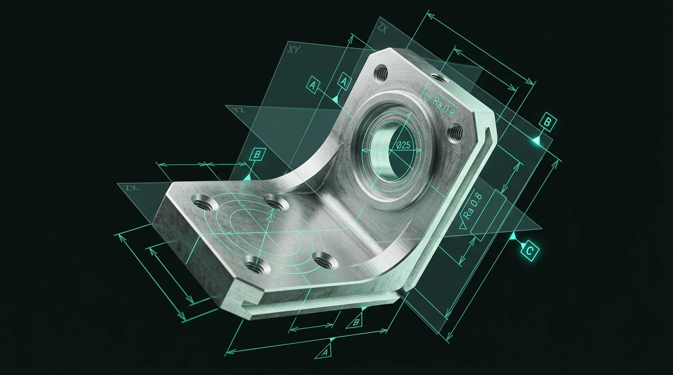
This is the prompt-writing companion to how to generate a STEP file from text, which covers the end-to-end workflow.
The six elements of a prompt that works
1. Part type and function
Start with what it is, in the vocabulary an engineer would use. "Flanged bearing housing", "L-bracket", "shaft coupling", "manifold block", "spacer" — these carry a great deal of implied structure. "A thing that holds a motor" carries none.
Function follows: what it mounts to, what it carries, what moves. This is what lets the system resolve the ambiguities you did not address.
2. Envelope and units
State the overall bounding dimensions with explicit units. Millimetres are the default assumption in mechanical CAD; if you mean inches, say so, and expect more errors either way.
If the envelope is a constraint rather than a preference — it has to fit a 120 mm gap — say that, because it changes what the generator is allowed to do with everything else.
3. Datum and orientation
This is the element most people skip and the one that causes the most rework. Say which face is the mounting face, which axis the bore runs along, where the origin sits. Without it, positions are ambiguous and the part may arrive rotated, mirrored, or measured from an unexpected corner.
"Base plate lies in the XY plane, mounting face down; the bore axis is vertical (Z)."
4. Features with size and position
Every feature needs both. A hole has a diameter and a location. A rib has a thickness, a height and an attachment. A pocket has dimensions and a depth from a named face.
The positional half is where descriptions usually fail:
| Under-specified | Specified |
|---|---|
| "Four mounting holes" | "Four Ø6.6 mm holes (M6 clearance, ISO 273 medium series) on a 60 × 30 mm rectangular pattern, centred on the plate" |
| "A central bore" | "Ø25 mm through bore on the plate centreline, axis along Z" |
| "A stiffening rib" | "One 5 mm thick rib on the centreline, from the base plate to 40 mm up the vertical wall" |
| "Rounded corners" | "R6 fillets on the four vertical outer corners" |
| "Countersunk holes" | "Four M5 countersunk holes for 90° heads, 15 mm from each edge" |
5. Process and material
"Machined from 6082-T6 aluminium", "injection moulded in glass-filled nylon", "3D printed in PETG", "laser cut from 3 mm mild steel". This single phrase determines minimum wall thickness, internal corner radii, draft, and whether undercuts are possible at all. The rules it activates are in DFM 101.
Naming the process is the highest-leverage sentence in most prompts.
6. Standard parts by designation
"M8×1.25 hex head bolt, property class 8.8." "6204 deep groove ball bearing." "ISO 4762 socket head cap screw, M6×20."
Designations are verifiable; descriptions are not. This matters because standard components have exact dimensions that a generator should look up rather than approximate — the argument is made in full in generating fasteners, gears and bearings.
Before and after
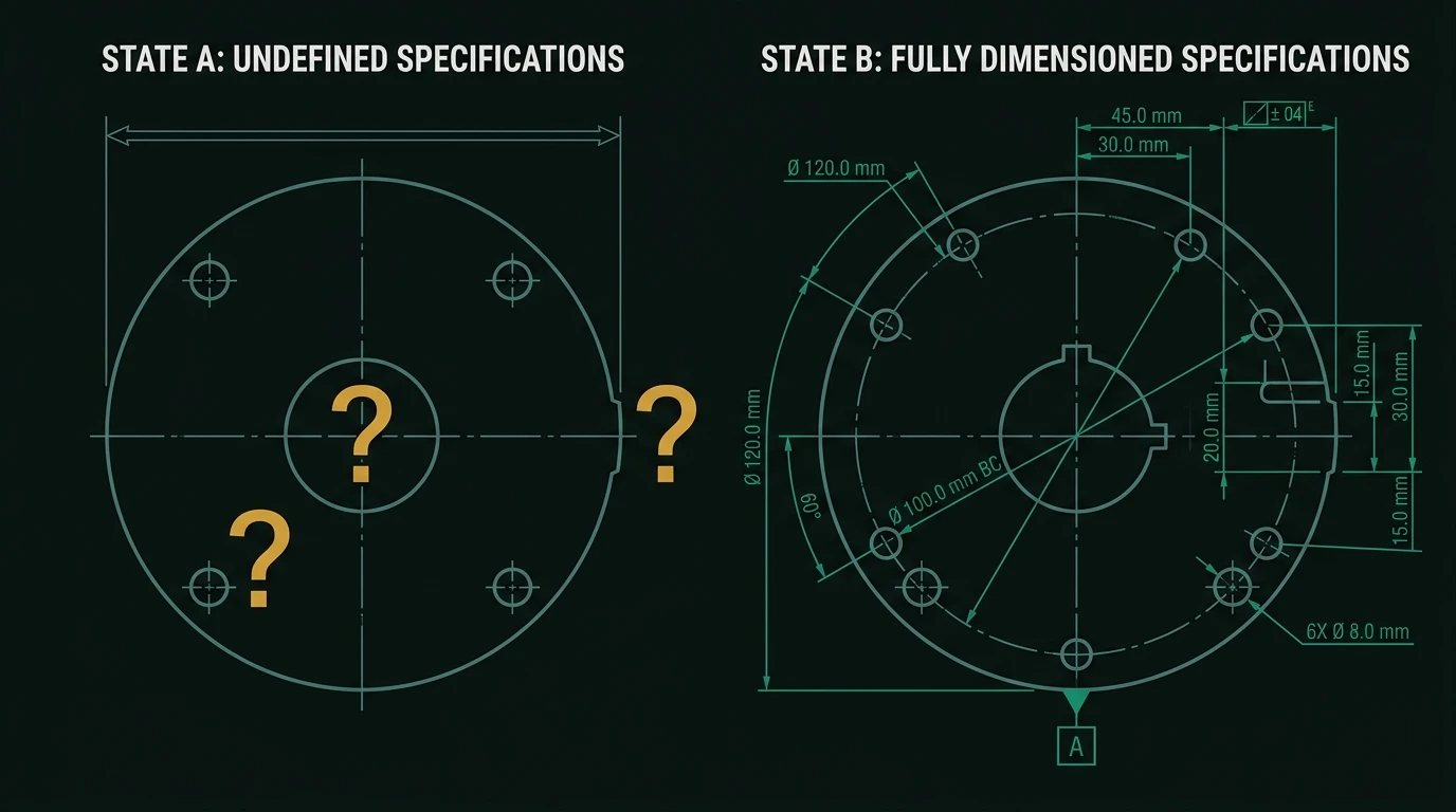
Before:
Design a bracket to mount a small motor to a frame.
Nothing here fixes a single dimension. Every number in the result will be assumed.
After:
An L-bracket machined from 6 mm 6082-T6 aluminium plate. Base plate 80 × 60 mm lying in the XY plane; vertical wall 80 × 50 mm rising in +Z from the long edge. Base plate has four Ø6.6 mm clearance holes for M6 on a 60 × 40 mm rectangular pattern, centred. Vertical wall has a Ø30 mm through bore for a motor pilot, centred 30 mm above the base, plus four M4 tapped holes on a Ø45 mm bolt circle concentric with the bore. R5 fillet at the internal corner between base and wall; R3 on external vertical corners.
Every dimension that interfaces with something else is stated. The generator still has room to resolve details, but nothing load-bearing is left to chance.
A second pair, for a turned part:
Before: "A shaft with a step and a keyway."
After: "A stepped shaft, machined from EN 1.4301 stainless, total length 120 mm. Ø20 mm over the first 70 mm, stepping down to Ø16 mm for the remaining 50 mm. A 5 × 5 mm parallel keyway, 30 mm long, starting 10 mm from the Ø20 end. 1 × 45° chamfers on both ends. The Ø20 section is a bearing seat and should be sized for a k6 fit."
The last sentence is doing real work: it tells the system that this diameter has a functional fit requirement, which is different from a free dimension. What that fit means is in the ISO fit system.
What to leave out
- Aesthetic adjectives. "Sleek", "robust", "professional" do not constrain geometry.
- Reasoning about why. "Because the previous version cracked" is useful context for a human and noise for a generator. State the consequence — "increase the rib thickness to 6 mm" — instead.
- Every fillet radius on a complex part. Specify the ones that matter structurally or for tool access; over-constraining raises the chance of a contradiction that cannot be satisfied.
- Tolerances as text on the model. Say where a fit is required, because that changes nominal geometry; do not expect a ±0.05 to be embedded in the solid. See tolerances AI tools get wrong.
- Multiple unrelated parts in one request. Generate an assembly component by component against a defined interface.
Iterating without going backwards
Once you have a nearly-right model, the temptation is to rewrite the whole description. Resist it.
- Change one thing. If you adjust five dimensions and the result gets worse, you have learnt nothing about which change caused it.
- Prefer a parametric edit over a regeneration. If the tool exposes driving dimensions, adjusting a value is deterministic; regenerating is a fresh sample and may change things you liked. This is exactly the benefit described in parametric CAD.
- Correct positions with references, not nudges. "Move the bore up" is ambiguous; "bore centre 35 mm above the base face" is not.
- When a feature is repeatedly wrong, restate it as its own sentence with size, position and reference face, rather than embedding it in a longer clause.
- Keep a record of what worked. A description that produced a good part is a reusable template for the next size.
A checklist before you press generate
- Part type named in engineering vocabulary?
- Units stated?
- Overall envelope given?
- Mounting face and axis orientation stated?
- Every feature has both a size and a position relative to a named reference?
- Manufacturing process and material named?
- Standard components given by designation?
- Functional fits identified (bearing seats, dowel holes, sliding surfaces)?
- Anything you did not state — are you comfortable with it being assumed?
That last question is the real one. A good tool will tell you which dimensions it assumed; if it does not, assume everything unstated is arbitrary and check it.
The bottom line
Prompting for CAD is specification writing, not conversation. Name the part, fix the units and envelope, declare a datum, give every feature a size and a position, name the process, and cite standard components by designation. Then verify the result against the checklist in why AI CAD fails on the shop floor — because a well-written prompt improves the odds, and does not remove the review.
Frequently asked questions
- How do I write a good prompt for text-to-CAD?
- Name the part type, give the overall envelope with units, describe each feature with its size and its position relative to a named reference, state the manufacturing process and material, and give standard components by their designation rather than by description. Anything you leave out will be assumed, so state the dimensions that interface with something else and let the rest be assumed.
- How much detail is too much in a CAD prompt?
- Detail that constrains geometry is useful; detail that describes intent is not. 'Bore 25 H7 concentric with the outer diameter' changes the model. 'Should look professional and be well designed' does not. Over-specifying every fillet radius also hurts, because it leaves no room for the generator to produce a coherent part and increases the chance of a contradiction it cannot satisfy.
- Should I specify tolerances in a CAD prompt?
- Specify fits where they matter functionally — a bearing seat, a dowel hole, a sliding interface — because that changes the nominal dimension the model should use. Do not expect the tolerance itself to be embedded in the geometry: most generated models carry nominal dimensions only, and the tolerance still belongs on a drawing or in a PMI-capable STEP AP242 workflow.
- Why did the generated model ignore part of my description?
- Usually because the description was ambiguous about position rather than about size. 'Four mounting holes' says how many but not where; 'a rib for stiffness' says why but not what shape or where it attaches. Features stated without a position relative to a named reference are the most commonly misplaced. Re-state them as offsets from a specific face or centreline.