What Is Parametric CAD? Constraints, Features, and Design Intent
Parametric CAD models are defined by driving dimensions and relationships instead of fixed coordinates. Here is how the feature tree, the constraint solver, and design intent actually work — and where regeneration breaks.
- Author:
- Cadagen
- Technical review:
- CADAGEN Engineering Team · Mechanical Engineer
- Last updated:
- August 15, 2026
- Sources:
- 2 primary references, listed below
Parametric CAD is a modelling method where geometry is driven by named parameters and explicit relationships rather than fixed coordinates — change one dimension and the whole model recomputes. It is the dominant paradigm in mechanical CAD (SolidWorks, Onshape, Fusion, Creo, NX, Inventor, FreeCAD), and the reason a well-built model can be resized into a family of parts in seconds while a badly-built one collapses on the first edit.
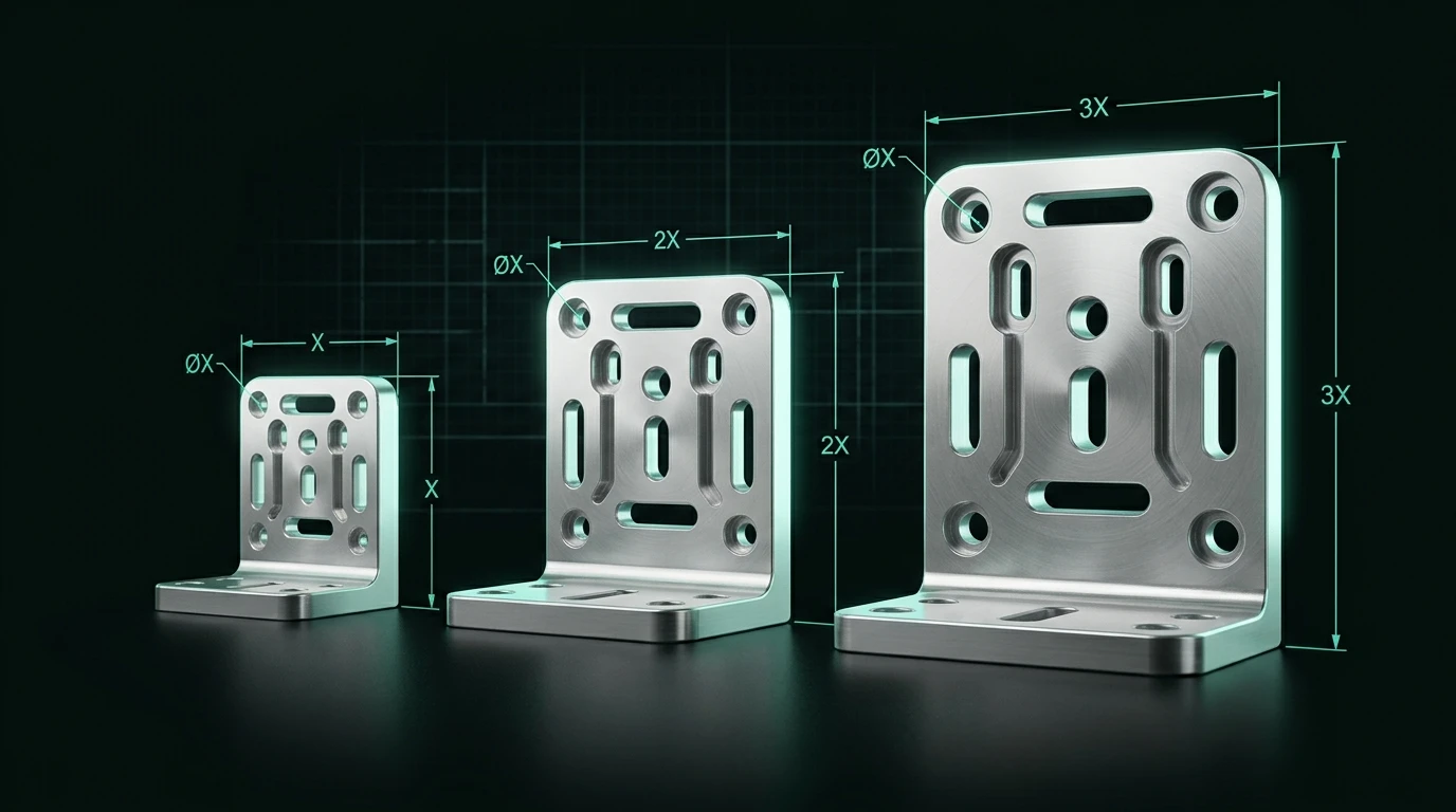
The core idea: dimensions drive geometry, not the other way around
In a non-parametric drawing you place a line from (0, 0) to (80, 0). The number 80 is a
consequence of where the line ends. In a parametric model you declare a parameter —
plate_width = 80 — and the line is constrained to be that long. The geometry is downstream of
the number.
That inversion is what makes everything else possible:
- One edit propagates. Set
plate_width = 120and the sketch, the extrusion, the hole pattern anchored to the edge, and the fillet all move together. - Relationships survive edits. A rule like "bolt circle diameter = flange OD − 2 × edge distance" stays true at every size.
- A model becomes a family. The same file produces M6, M8 and M10 variants by changing a configuration value rather than by cloning and hand-editing.
The three machines under the hood
Most people meet parametric CAD as a UI. Underneath, three distinct systems are cooperating.
1. The sketch constraint solver
A 2D sketch is a set of entities plus constraints: coincident, horizontal, tangent, equal, concentric, symmetric, plus dimensional constraints. The solver looks for a configuration that satisfies all of them simultaneously.
A sketch is fully constrained when exactly one solution exists — every degree of freedom is removed. Under-constrained sketches are the single most common source of models that "move on their own" when a parameter changes. Over-constrained sketches are the second, because the solver is handed contradictory requirements and refuses (or silently drops one).
2. The feature tree (history)
Features — extrude, revolve, sweep, loft, hole, fillet, chamfer, shell, pattern — are recorded in order. Each one consumes the result of the previous. Changing a parameter triggers a regeneration: the system replays the list from the point of change forward.
This is why feature order matters. A shell applied before a boss produces a different part than a shell applied after it, even with identical parameters.
3. The geometric kernel
Underneath both sits the modelling kernel — Parasolid, ACIS, Open CASCADE (OCCT), or a vendor-internal equivalent — which performs the actual boolean operations, filleting and surface intersection on boundary representation (B-Rep) solids. The kernel is why parametric CAD produces exact, manufacturable geometry rather than a triangle approximation. See B-Rep vs. mesh for what that distinction buys you downstream.
Parametric vs direct vs mesh modelling
| Parametric (history-based) | Direct modelling | Mesh modelling | |
|---|---|---|---|
| Geometry defined by | Parameters + constraints + ordered features | The current B-Rep faces themselves | Triangle vertices |
| Editing a dimension | Change the value, regenerate | Push/pull the face; no history | Not meaningful — no dimensions exist |
| Design intent captured | Yes, explicitly | No | No |
| Handles imported files well | Poorly (no history to inherit) | Very well | N/A |
| Typical failure | Regeneration / rebuild error | Silent loss of intent | Facet artefacts, non-manifold edges |
| Best for | Parts that will be revised or scaled | One-off edits, imported STEP, quick concept work | Visualisation, 3D printing input |
Most modern CAD systems are hybrids: you can drop direct edits into a parametric history, and most parametric systems can push-pull imported geometry. The distinction is about where the authority lives, not about which buttons exist.

Design intent is the part people skip
"Design intent" sounds like consultant vocabulary, but it has a concrete test: if a colleague changes one dimension, does the model still mean what you meant?
Consider a mounting plate with four holes. Three ways to place them:
- Absolute coordinates. Hole centres at (10, 10), (70, 10), (10, 30), (70, 30). Widen the plate and the holes stay bunched at one end.
- Dimensioned from one edge. Better, but asymmetric growth still breaks the pattern.
- Symmetric about the plate centreline, with edge distance as a parameter. Widen the plate and the pattern spreads correctly, because you encoded why the holes are where they are.
Only the third model survives a design review. The geometry is identical in all three cases; the difference only shows up on the first edit — which is exactly when it costs money.
A practical rule: every dimension should answer "what physically determines this?" Edge distance is determined by bolt head clearance and tear-out margin. Bolt circle is determined by the mating flange. Wall thickness is determined by the process, as covered in DFM 101.
Where parametric models actually break
Parametric CAD has well-known failure modes, and knowing them is most of what separates a robust model from a fragile one.
Regeneration failures. A fillet that fit at 80 mm has no room at 40 mm; a boolean that produced a valid solid now produces a zero-thickness wall. The model errors out, and the error usually appears several features downstream of the real cause.
The topological naming problem. When a feature references "face 17", and an earlier edit changes how many faces exist, "face 17" may now be a different face. The later feature then attaches to the wrong place — or fails. This is a genuinely hard kernel problem, not a user error; commercial kernels invest heavily in persistent naming heuristics, and open-source projects have documented long-running efforts to improve it. The defensive practice is to select geometry by rule rather than by pick: "all edges parallel to Z", "the largest planar face", "faces created by this specific feature".
Constraint drift in large assemblies. Mates and in-context references create dependency chains across files. A change three parts away can trigger a rebuild you did not anticipate.
Over-parameterisation. A model with 90 driving parameters is not more flexible than one with 9 — it is less usable, because nobody knows which ones are safe to change. Expose the parameters that correspond to real requirements and derive the rest.
Parametric CAD and generated models
This matters for AI-assisted CAD specifically. A tool that outputs a mesh gives you a shape you cannot edit dimensionally. A tool that outputs a parametric description — a script, a feature sequence, or a set of exposed driving dimensions — gives you a model you can adjust after the fact.
That is why the useful question about any generative CAD tool is not "does it look right?" but "which dimensions can I change afterwards, and does the rest of the model follow?" A single adjustable parameter that only rescales the whole part uniformly is not parametric modelling; it is a scale factor.
If a generated model exposes its driving dimensions, you can verify a fit, correct a wall thickness, or match a real mating part without regenerating from scratch. If it does not, every correction is a new generation and a new review cycle. The related discussion of representation is in text-to-CAD vs text-to-3D, and the code-driven version of parametric modelling is covered in code CAD.
Common mistakes
- Leaving sketches under-constrained and relying on the solver's arbitrary choice.
- Dimensioning to construction artefacts (a projected edge that will disappear) instead of to stable references.
- Building the whole part in one giant sketch, which makes every change a re-draw.
- Filleting too early. Fillets consume edges that later features want to reference; add them late unless the geometry genuinely depends on them.
- Modelling manufacturing features that do not exist yet — threads modelled as full helical geometry, for instance, bloat the file and slow every rebuild without improving the drawing. See ISO metric thread sizes for how threads should actually be specified.
- Confusing a configuration with a parameter. Configurations select between discrete states; parameters vary continuously. Using configurations for a continuous dimension produces unmaintainable tables.
The bottom line
Parametric CAD is not "CAD with numbers in it" — it is CAD where the numbers, and the relationships between them, are the model. The payoff is that a change costs one edit instead of a redraw; the price is that a model built without design intent will fail on the first revision. Build the relationships deliberately, constrain sketches fully, select geometry by rule rather than by pick, and expose only the parameters that correspond to real requirements.
In CADAGEN those driving sizes can become sliders after a successful run — see how to change dimensions with sliders.
Frequently asked questions
- What is parametric CAD in simple terms?
- Parametric CAD is a modelling approach where a part's shape is driven by named parameters and geometric relationships rather than fixed coordinates. Changing one value — say a plate width from 80 mm to 120 mm — makes the CAD system recompute every dependent feature, so hole patterns, fillets and mating faces move with it instead of being redrawn by hand.
- What is the difference between parametric and direct modelling?
- Parametric (history-based) modelling records an ordered list of features and replays it whenever a parameter changes, which preserves design intent but can fail on regeneration. Direct modelling edits the resulting geometry itself — push, pull, offset a face — with no history to replay. Direct modelling is faster for one-off edits and imported files; parametric modelling is better when the part will be revised repeatedly or exists as a family of sizes.
- Is a STEP file parametric?
- No. A STEP file carries the resulting boundary representation (exact faces, edges and vertices) plus optional product data, but not the feature tree or the parameter equations that produced it. When you open a STEP file in a CAD system you get editable solid geometry, not the original sketch dimensions. That is why STEP is called a neutral exchange format rather than a native format.
- What is the topological naming problem?
- It is the failure mode where a feature references a face or edge by an internal identifier, and a change earlier in the history renumbers that entity — so the later feature attaches to the wrong face or fails outright. Mature commercial kernels mitigate it with persistent naming heuristics, and robust modelling practice avoids it by selecting geometry through stable rules (largest face, edges parallel to an axis) instead of individual picks.