Code CAD: Defining Mechanical Parts in Code Instead of a Mouse
Code CAD replaces the sketch-and-click workflow with a script that builds the part. Here is the tool landscape, the CSG-vs-B-Rep split that decides whether you get a STEP file, and when scripting genuinely beats a GUI.
- Author:
- Cadagen
- Technical review:
- CADAGEN Engineering Team · Mechanical Engineer
- Last updated:
- August 15, 2026
- Sources:
- 3 primary references, listed below
Code CAD means defining a part in a text program — parameters, operations, exports — instead of drawing it with a mouse. The script is the model: run it and you get geometry, edit a number and re-run it and you get a different size, commit it to Git and you get a reviewable history of every design change.

It is not a new idea (OpenSCAD dates to 2010, and CAD APIs are older still), but it has become substantially more relevant for two reasons: modern Python libraries now drive a real boundary-representation kernel rather than a mesh engine, and large language models are far better at writing code than at emitting geometry directly.
What a code CAD script actually looks like
The pattern is nearly identical across tools: declare parameters, build primitives, combine them, select geometry to modify, export.
from build123d import *

plate_l, plate_w, plate_t = 80.0, 40.0, 10.0
hole_d, edge_dist = 6.0, 10.0
x, y = plate_l / 2 - edge_dist, plate_w / 2 - edge_dist

with BuildPart() as plate:
    Box(plate_l, plate_w, plate_t)
    with Locations((x, y), (-x, y), (x, -y), (-x, -y)):
        Hole(radius=hole_d / 2)
    fillet(plate.edges().filter_by(Axis.Z), radius=5)

export_step(plate.part, "plate.step")
Three things in that snippet are worth noticing, because they are what code CAD is for:
- The dimensions are named variables. Changing
plate_lregenerates everything downstream — the same behaviour as a well-built parametric model, expressed in a dozen lines. - Geometry is selected by rule, not by pick.
edges().filter_by(Axis.Z)means "every edge parallel to Z", which stays correct when the plate changes size. This sidesteps the topological naming problem that plagues history-based GUI models. - The output is a STEP file — an exact solid, not a mesh, because the library is driving a B-Rep kernel.
The landscape: which tool produces what
The single most consequential difference between code CAD tools is the geometry engine underneath. It determines the export formats you can produce and whether operations like true fillets exist at all.
| Tool | Language | Geometry engine | Native STEP export | Best suited to |
|---|---|---|---|---|
| OpenSCAD | Own declarative DSL | CSG → mesh | No (STL / 3MF / OFF / AMF) | 3D-printed parts, printable part families, hobby and rapid fixtures |
| CadQuery | Python | Open CASCADE (B-Rep) | Yes | Machined parts, STEP deliverables, scripted part families |
| build123d | Python | Open CASCADE (B-Rep) | Yes | Same as CadQuery, with a more explicit topology and geometry API |
| FreeCAD Python API | Python | Open CASCADE (B-Rep) | Yes | Scripting inside a full GUI CAD system; headless batch via FreeCADCmd |
| JSCAD | JavaScript | CSG → mesh | No | Browser-based configurators, web-embedded parametric models |
| replicad | JavaScript / TypeScript | Open CASCADE (WASM) | Yes | Browser-based B-Rep modelling, web configurators needing STEP |
| Onshape FeatureScript | FeatureScript | Onshape's kernel | Via Onshape export | Custom features inside Onshape, enterprise standard-part libraries |
| CAD vendor APIs (Fusion, SolidWorks, NX, Inventor) | Python / C# / C++ / VBA | Host CAD kernel | Via the host application | Automating an existing seat of CAD, drawing and BOM generation |
For the two most-compared options, see build123d vs CadQuery; for the mesh-versus-B-Rep decision specifically, see OpenSCAD vs Python CAD.
CSG vs B-Rep, in one paragraph
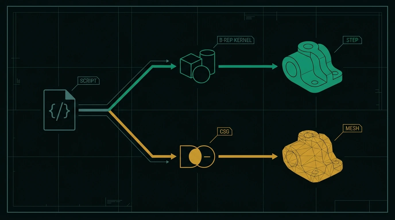
Constructive solid geometry describes a shape as a tree of boolean operations on primitives ("cylinder minus box, unioned with sphere"). It is straightforward to implement and robust, but the evaluated result is a mesh, and there is no exact face or edge to attach a true fillet or a tolerance to. Boundary representation stores the actual analytic surfaces and trimmed curves, so a 6 mm hole is a real cylindrical face with a real radius. Everything downstream — STEP export, CAM toolpaths, GD&T, mating in an assembly — depends on that distinction. The full comparison is in B-Rep vs. mesh.
Why engineers move work into code
Version control that actually works. A native CAD part file in Git is an opaque binary blob; you can store it, not review it. A 90-line script produces a diff a colleague can read in a pull request: "wall thickness 2.5 → 3.0, added draft on the outer face". Design review becomes code review.
Part families for free. Generating 40 bracket variants is a for loop, not 40 save-as
operations. This is where scripted CAD pays back fastest — see
automating repetitive CAD tasks.
Geometry you can test. Because the script runs headless, you can assert on the result in CI: volume within an expected range, bounding box matches the envelope, the solid is watertight, the body count is what you expected. Nothing in a GUI workflow gives you a regression test that fails when someone breaks the model.
def test_plate_envelope():
    part = build_plate(length=80, width=40)
    bbox = part.bounding_box()
    assert abs(bbox.size.X - 80) < 1e-6
    assert part.volume > 0
Integration with everything else. A script can read a spreadsheet of customer dimensions, pull a supplier's bearing bore from a database, compute a wall thickness from a stress calculation, and emit the STEP — in one process. That is difficult to arrange around a GUI.
Reproducibility. The same script, same library version, same inputs produces the same geometry. For anything audited or regulated, that matters more than convenience.
Why code CAD is not the default
Honesty about the trade-offs is more useful than advocacy.
- No visual exploration. You cannot feel out a shape by dragging it. Every idea has to be articulated before you see it, which is slow for concept work and genuinely painful for aesthetic surfacing.
- Assemblies are weaker. Mates, interference detection and kinematics are first-class in GUI CAD and mostly manual — placements and transformations — in code CAD.
- Drawings are a gap. Producing a dimensioned 2D drawing with GD&T from a script is possible but far behind what a GUI system does in minutes. See GD&T basics for what those drawings have to carry.
- Free-form surfacing is limited. Class-A surfaces, complex lofts and curvature-continuous blends remain GUI territory.
- The debugging loop is different. A boolean that fails produces a stack trace, not a highlighted red face. Reading kernel errors is a learned skill.
- Fragility at the edges. Fillet and chamfer operations on complex intersections can fail in ways that require restructuring the script rather than nudging a value.
A useful heuristic: if the part will exist once, draw it; if it will exist in forty variants or be regenerated by another program, script it.
Code CAD and AI-generated models
Code CAD has become disproportionately important to AI-assisted CAD for a structural reason: language models are trained overwhelmingly on text and code, and are far more reliable at producing a syntactically valid program than at emitting valid B-Rep topology directly. So the practical architecture for most text-to-CAD systems is language → generation script → kernel → CAD file, not language → geometry.
That has three useful consequences:
- The intermediate artefact is inspectable. A script can be read, diffed and corrected; a raw solid cannot.
- Failures are catchable. A script that does not run, produces an empty solid, or violates a wall-thickness rule can be rejected before anyone downloads it.
- Parameters survive. Because the script has named variables, the resulting model can expose real driving dimensions rather than a single uniform scale factor.
The full mechanics of that pipeline are in how LLMs generate CAD, and what still goes wrong is in what actually breaks.
Common mistakes when starting out
- Hard-coding derived values. If the bolt circle is
flange_od - 2 * edge_dist, write that expression, not62.5. The whole point is that the relationship survives an edit. - Selecting geometry by index.
edges()[3]breaks the moment the geometry changes. Filter by axis, position, length or the face that produced them. - Filleting everything at the end with one radius. Kernel fillet failures are usually caused by asking for a radius that does not physically fit at some edge. Fillet in groups.
- Ignoring units. Most libraries treat numbers as unitless and interpret them as millimetres by convention; STL in particular carries no units at all. See generating STL files.
- Exporting the builder instead of the shape. In several libraries the builder object is not itself a solid; exporting it fails with a confusing message. Export the resulting part.
- Skipping validation. A script that runs successfully can still produce a shape with zero volume or disconnected bodies. Assert on volume, bounding box and body count.
The bottom line
Code CAD is parametric modelling with the parameters and relationships written down in a language a computer and a colleague can both read. Choose a B-Rep-backed tool if the deliverable is a STEP file for manufacturing, and a CSG tool if the deliverable is a printable mesh. Use it where repetition, generation, testing or integration is the point — and keep a GUI seat for exploration, surfacing, assemblies and drawings.
Frequently asked questions
- What is code CAD?
- Code CAD (also called programmatic or script-based CAD) is the practice of defining a 3D model in a text program rather than through a graphical sketch-and-feature interface. The script declares parameters, builds geometry with operations like extrude, fillet and boolean subtract, and exports a CAD file. Because the model is source code, it can be version-controlled, diffed, tested and generated automatically.
- Does code CAD produce real CAD files or just meshes?
- It depends on the underlying kernel. Tools built on a boundary-representation kernel such as Open CASCADE — CadQuery, build123d, FreeCAD's Python API — produce exact B-Rep solids and can export STEP. Constructive-solid-geometry tools such as OpenSCAD work toward a mesh and export STL, 3MF or OFF, with no native STEP output. If you need a file a machine shop can use directly, that distinction is the first thing to check.
- Is code CAD better than traditional CAD?
- Neither is universally better. Code CAD wins on part families, repeatable generation, version control, automated testing and integration with other software. Traditional GUI CAD wins on free-form exploration, complex surfacing, assembly mating, drawing production and anything where seeing the result while you drag a dimension is the point. Many teams use both: scripts for generated families, a GUI for one-off design work.
- Do I need to be a programmer to use code CAD?
- For OpenSCAD, no — its language is small and purpose-built, and many mechanical engineers learn it in an afternoon. For Python-based libraries like CadQuery and build123d you need basic Python: variables, loops, functions and imports. You do not need software-engineering depth, but you do need to be comfortable reading an error message and looking up an API reference.
References
- build123d - Introductory examples (Hole, fillet, GridLocations selectors) — build123d docs
- CadQuery - QuickStart (Workplane, forConstruction, hole) — CadQuery docs
- OpenSCAD User Manual - Export formats (STL, OFF, AMF, 3MF, DXF, SVG, PDF) — OpenSCAD manual