B-Rep vs. Mesh: Why Editable Geometry Actually Matters
The practical difference between boundary representation (B-Rep) solids and triangle meshes — and why the distinction determines whether a generated model can be edited, toleranced, or machined at all.
- Author:
- Cadagen
- Technical review:
- CADAGEN Engineering Team · Mechanical Engineer
- Last updated:
- August 16, 2026
- Sources:
- 3 primary references, listed below
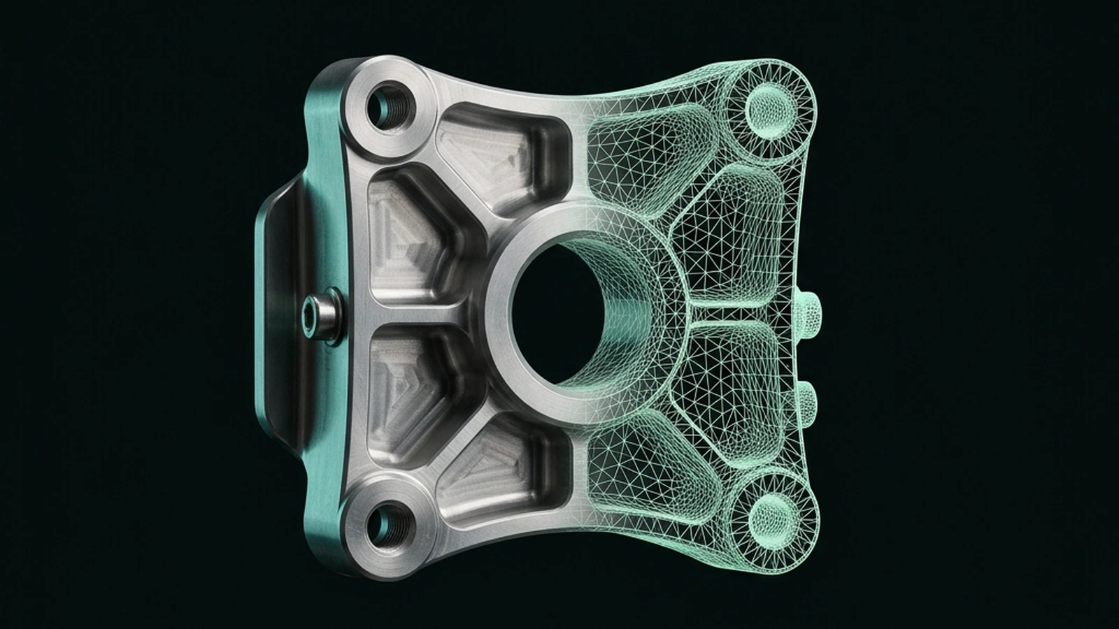
A B-Rep (boundary representation) solid describes a part's geometry as exact mathematical surfaces — planes, cylinders, splines — bounded by precise edges. A mesh describes the same shape as a collection of flat triangles approximating that surface. They can look identical rendered on screen and be fundamentally different underneath, and that difference decides whether a file is usable for engineering work or only for visualization.
What each format actually stores
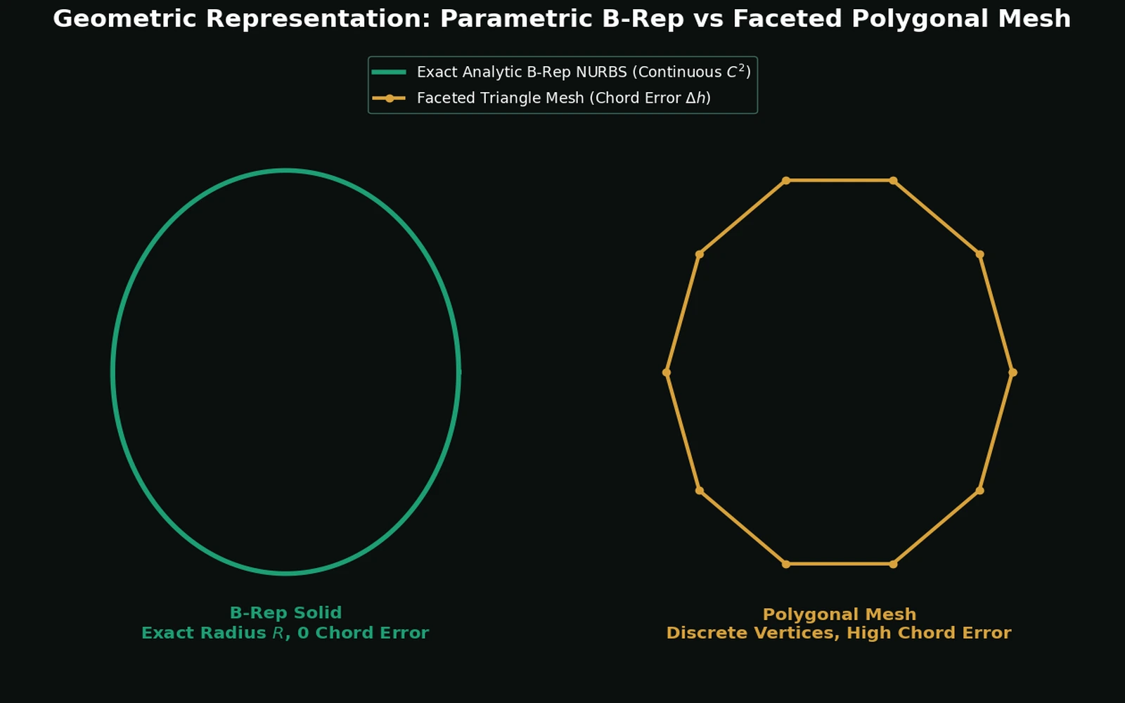
A B-Rep solid is built from a hierarchy: faces (bounded by exact mathematical surfaces), edges (exact curves where faces meet), and vertices (exact points where edges meet), plus the topological information describing how they connect into a closed volume. A cylindrical hole in a B-Rep model is stored as an actual cylinder — a mathematically exact surface with a radius and an axis — not an approximation.
A mesh discards all of that exactness in favor of a simpler, uniform representation: every surface, curved or flat, is broken into flat triangular facets. The same cylindrical hole in a mesh is approximated by dozens or hundreds of small flat triangles arranged to look roughly cylindrical from a normal viewing distance.
Why this distinction isn't just academic
You can't reliably edit a mesh the way you edit a B-Rep
In a B-Rep model, "make this hole 12 mm instead of 10 mm" is a parameter change — the software regenerates the exact cylindrical surface at the new radius, and everything downstream (fillets, patterns, other features referencing that hole) updates correctly. In a mesh, there's no "hole parameter" to change — there are just triangles that happen to be arranged in a roughly circular pattern. Modifying the size means manually manipulating hundreds of individual triangle vertices, or regenerating the whole mesh from a different source. This is why every serious CAD package (native or via STEP import) works on B-Rep data, not mesh, for anything that needs later modification.
Mesh geometry doesn't carry exact dimensions
Ask a mesh "what is the diameter of this hole" and you get an estimate, computed by fitting a circle to the triangle vertices that approximate the hole's edge — it's not stored anywhere as an exact number, because the mesh never had one. A B-Rep model stores the actual radius as a parameter of the cylindrical surface. For anything requiring dimensional accuracy — a manufacturing drawing, a tolerance callout, a CMM inspection program — this matters enormously: you need the actual dimension, not a best-fit approximation of a faceted surface.
Manufacturing processes need real surfaces, not facet approximations
A CNC toolpath for a curved surface needs to follow the actual mathematical curve to produce a smooth result — following a faceted mesh approximation instead produces visible flat spots ("facet marks") on the finished part, because the tool is literally tracing flat triangles instead of the intended curve. Injection mold tooling, casting patterns, and precision-machined parts all need B-Rep geometry for this reason. Mesh is fine for 3D printing (where the printer itself works in discrete layers anyway) and for visualization, but it's the wrong representation for processes that can actually reproduce continuous curved surfaces.
A side-by-side comparison
| B-Rep (STEP, native CAD formats) | Mesh (STL, OBJ) | |
|---|---|---|
| Geometry stored as | Exact mathematical surfaces + topology | Flat triangle facets approximating the surface |
| Editable after export | Yes — dimensions and features can be modified | No — requires manual triangle manipulation or full regeneration |
| Dimensional accuracy | Exact, to the precision of the modeling kernel | Approximate, degrades with coarser triangulation |
| Best suited for | Machining, casting, tolerance analysis, further design iteration | 3D printing, rendering, visualization, simulation meshing |
| File size for complex curved geometry | Compact — a cylinder is one parametric surface | Large — a smooth curve needs many small triangles to look smooth |
| Typical formats | STEP (.stp/.step), IGES, native (SLDPRT, etc.) | STL, OBJ, 3MF |
The knob that controls how bad the approximation is: chord height
When a mesh is generated from a B-Rep model (exporting to STL, or building a preview in a viewer), the exporter doesn't pick triangle size arbitrarily — it works to a chord height tolerance (also called surface deviation): the maximum allowed distance between the true curved surface and the flat triangle standing in for it. A tighter chord height forces smaller triangles and a closer approximation, at the cost of triangle count and file size; a looser one produces a visibly faceted surface with a smaller file. This is exactly why "the STL looked fine in the viewer" is not a strong claim — a coarse export with a loose chord height can look acceptable at typical zoom levels while still deviating from the true surface by a fraction of a millimetre, which matters once that surface has to seat against another part or hold a press fit. Refining the chord height reduces this deviation; it never makes it exactly zero, because a flat triangle can only ever approach a curved surface, not equal it — which is the practical version of the point above that a mesh is never truly exact regardless of resolution.
Where the confusion usually comes from
Rendered on screen, a fine mesh and a B-Rep solid can be visually indistinguishable — both look like a smooth curved surface if the triangle count is high enough. This is exactly why the difference gets glossed over in casual conversation and even in some marketing material: "3D model" doesn't distinguish between them, but "3D model I can machine and re-edit" versus "3D model I can only print or look at" are very different deliverables. See our companion guide on STEP vs. STL for the format-level version of this same distinction.
Why this matters specifically for generated CAD
A tool that produces a mesh output — even a very fine, visually convincing one — hasn't actually given you an editable engineering model, no matter how good it looks in a viewer. It's given you a snapshot. If your workflow needs to open the file in SolidWorks, Fusion, or Inventor and adjust a dimension, apply a tolerance, or generate a 2D drawing from it, you need B-Rep output — which means the generation process itself has to work with real parametric surfaces internally, not just produce a mesh that happens to resemble the intended shape.
A quick test to check what you actually have
If you're unsure whether a file is genuinely B-Rep or a mesh wearing a CAD file extension: open it in any CAD package and try to select a single curved face and read its exact radius, or try to apply a fillet along one of its edges. A true B-Rep model reports an exact radius and fillets cleanly. A mesh either won't let you select "a face" in the same way (only individual triangles) or will report an approximate, slightly inconsistent radius depending on which triangles you sampled.
The bottom line
Mesh and B-Rep aren't two flavors of the same thing — they're solving different problems. Mesh answers "what does this look like." B-Rep answers "what exactly is this, and can I still change it." For anything headed toward CNC machining, injection molding, or further design iteration, only B-Rep geometry — delivered as STEP or a native CAD format — actually qualifies as an engineering deliverable.
Sources: Wikipedia — Boundary representation · ISO 10303-242:2020 — Managed model-based 3D engineering · prostep ivip — STEP AP242 · our own What Is a STEP File? and STEP vs. STL guides.
Frequently asked questions
- What is B-Rep in CAD?
- B-Rep (boundary representation) describes a solid by its exact boundary: analytic surfaces such as planes, cylinders and tori, trimmed by real curves and joined at real vertices. Because the surfaces are exact rather than approximated, a hole has a genuine radius you can measure, tolerance and machine from. It is the representation used by essentially all mechanical CAD kernels.
- Why is a mesh not good enough for engineering?
- A mesh stores only triangle vertices, so there is no dimension to read, no face to select for a fit, and no curve for a CAM system to follow. A circular hole becomes a many-sided polygon that is always slightly undersized. That is acceptable for visualisation and most 3D printing, and unacceptable for machining, tolerancing or assembly mating.
- Can a mesh ever be exact?
- No. Refining the tessellation reduces the deviation between the triangles and the true surface but never eliminates it, and each refinement multiplies the file size. Exactness is a property of the representation, not of the resolution.
References
- Boundary representation - Wikipedia — Wikipedia
- ISO 10303-242:2020 - Managed model-based 3D engineering — ISO
- Fact Sheet: ISO 10303-242 (STEP AP242) — prostep ivip