What Is a STEP File? An Engineer's Guide (AP203, AP214, AP242)
STEP (ISO 10303) explained for mechanical engineers: what it stores, when to use it, and how it differs from mesh formats.
- Author:
- Cadagen
- Technical review:
- CADAGEN Engineering Team · Mechanical Engineer
- Last updated:
- August 16, 2026
- Sources:
- 7 primary references, listed below
A STEP file (ISO 10303) is a neutral CAD exchange format that stores precise solid geometry — faces, edges, and surfaces — so you can open the same model in SolidWorks, Fusion, Inventor, CATIA, or FreeCAD and edit it like native geometry.

Why engineers use STEP
- Vendor-neutral: Your supplier does not need your native CAD license.
- B-Rep solids: Unlike STL, STEP carries editable topology, not just triangles.
- Manufacturing handoff: Machining, casting, and inspection workflows expect solids with real dimensions.
AP203 vs AP214 vs AP242
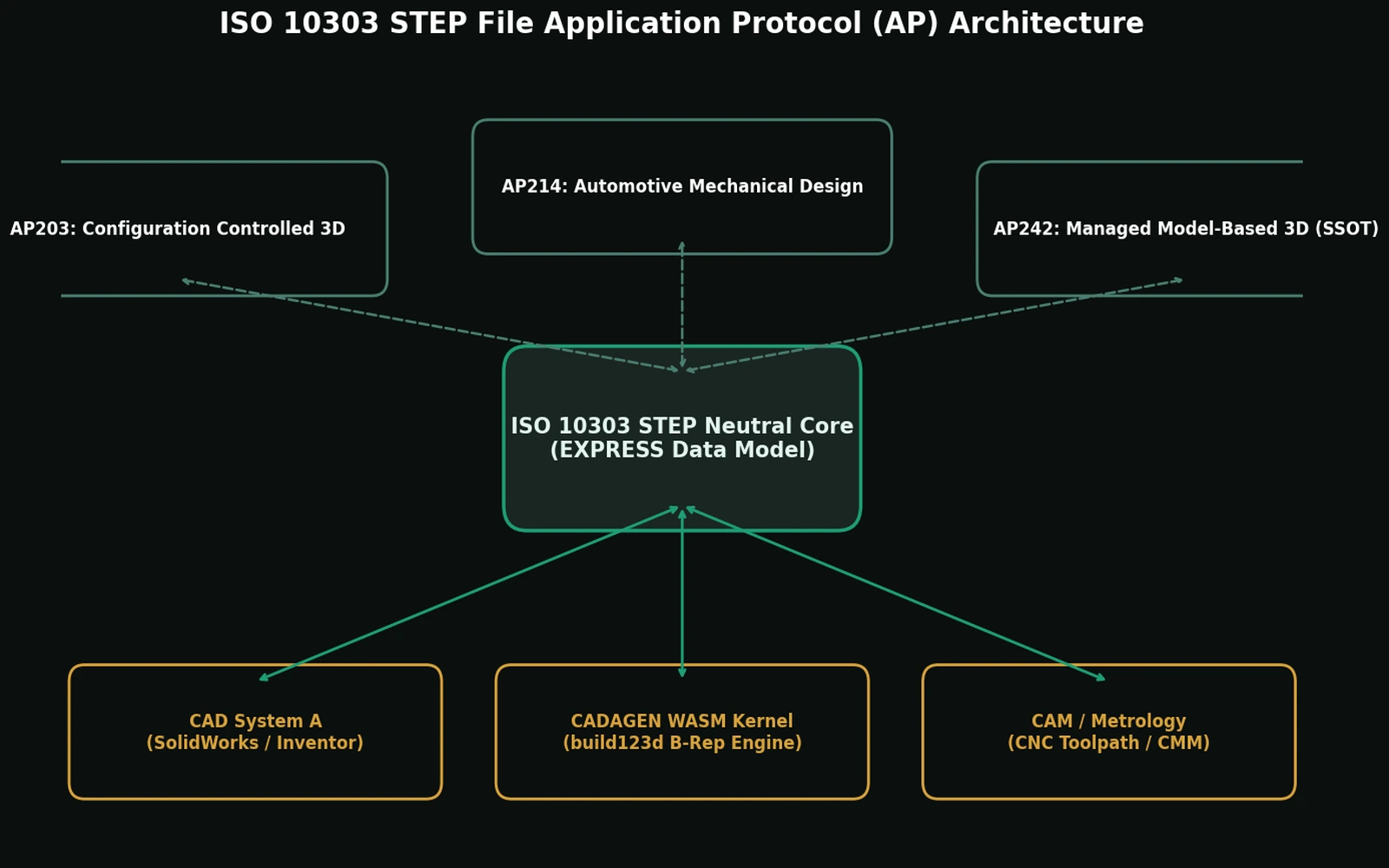
| Application protocol | Typical use |
|---|---|
| AP203 | General mechanical design, configuration — historically aerospace/defense-heavy |
| AP214 | Automotive-style design with more PMI hooks |
| AP242 | Modern exchange: consolidates AP203+AP214 scope, richer PMI, tessellation, long-term archiving |
Important context: ISO 10303-242 (Managed model-based 3D engineering) is the industry successor that converges the older AP203 and AP214 tracks. prostep ivip notes that AP242 Edition 1 (2014) already covered the functionalities of AP203 ed2 and AP214 ed3, then Edition 2 (2020) extended PDM, 3D PMI, composites, and related domains. For most shop-floor handoffs, any common AP203/AP214 export from a serious CAD tool is still acceptable if dimensions and units are correct. Reach for AP242 specifically when you need PMI (tolerance and inspection data) embedded directly in the file rather than communicated separately on a 2D drawing — or when long-term archival interoperability is a procurement requirement.
What's actually inside a STEP file
Open one in a text editor and you'll find a dense, machine-oriented text format — not something you're meant to read directly, but worth understanding at a high level. Every face, edge, and vertex is described as an exact mathematical entity (a plane, a cylinder, a B-spline surface) along with the topology describing how they connect into a closed volume. A cylindrical hole isn't approximated by anything — it's stored as an actual cylinder with a real axis and radius. This is precisely why you can open a STEP file in a different CAD package and still change a hole's diameter as a clean parameter edit: the diameter was never approximated to begin with.
The anatomy, concretely
Open any .step file in a text editor and you will see this skeleton:
ISO-10303-21;
HEADER;
  FILE_DESCRIPTION(('...'), '2;1');
  FILE_NAME('bracket.step', '2026-08-16T09:12:44', ('A. Engineer'),
            ('Acme'), 'preprocessor', 'originating system', '');
  FILE_SCHEMA(('AUTOMOTIVE_DESIGN { 1 0 10303 214 2 1 1 }'));
ENDSEC;
DATA;
  #1 = CARTESIAN_POINT('', (0., 0., 0.));
  #2 = DIRECTION('', (0., 0., 1.));
  #10 = MANIFOLD_SOLID_BREP('bracket', #9);
ENDSEC;
END-ISO-10303-21;
The rules are simple enough to read by eye. The HEADER carries exactly three mandatory
entities, always in this order: FILE_DESCRIPTION, FILE_NAME and FILE_SCHEMA. The DATA
section is a list of numbered instances — #id = ENTITY(arguments); — where an argument can be a
number, a quoted string, a list in parentheses, an enumeration written between dots (.T.,
.F.), or a reference to another instance (#9). An unset value is written $. That reference
graph is the model: a solid points at its shell, the shell at its faces, the faces at their
surfaces and edges, all the way down to individual points.
Two things you can check without opening CAD
This matters because two of the most expensive questions about a received file can be answered with a text search, before you burn a CAD licence and half an hour.
Which application protocol is it? Read FILE_SCHEMA. The schema string names the AP:
Schema string in FILE_SCHEMA |
Application protocol |
|---|---|
CONFIG_CONTROL_DESIGN |
AP203, first edition |
AP203_CONFIGURATION_CONTROLLED_3D_DESIGN_OF_MECHANICAL_PARTS_AND_ASSEMBLIES_MIM_LF |
AP203, second edition (2011) |
AUTOMOTIVE_DESIGN |
AP214 |
AP242_MANAGED_MODEL_BASED_3D_ENGINEERING_MIM_LF |
AP242 (all editions) |
The AP242 schema name is the same across its editions; the trailing ASN.1 identifier is what differs between first, second and third edition files.
Did you actually receive a solid? Search the DATA section for the entity that carries the
shape:
| Entity you find | What you actually have |
|---|---|
MANIFOLD_SOLID_BREP |
A closed solid — the thing you want |
BREP_WITH_VOIDS |
A solid with internal cavities; still a solid |
FACETED_BREP |
A solid, but with planar faces only |
SHELL_BASED_SURFACE_MODEL |
Surfaces, not a solid — may not be watertight |
GEOMETRIC_CURVE_SET |
Wireframe only; no faces at all |
A file whose shape lives in SHELL_BASED_SURFACE_MODEL is the classic "it opened, but CAM
rejects it" case: the receiving system reads it as a collection of shells rather than a solid
body, and any gap between those shells has to be found and stitched before the part can be
machined. Knowing this in advance changes who you email and what you ask for.
Common problems when opening a STEP file
- "Not a solid" errors. Some STEP files, due to an export error upstream, end up as an open shell rather than a closed volume. The file can look completely normal in a viewer and still fail to import as a solid, because CAM and simulation software need a genuine watertight boundary to know what's inside vs. outside the part.
- Unit mismatches. STEP files carry their own unit definition (mm, inch), but a small number of poorly generated files get this wrong — a part can open 10x too large or too small. Checking one known dimension right after import is a cheap habit that catches this immediately.
- Version compatibility. Very old CAD installations may not read every AP242 feature correctly. Falling back to AP203 is usually the safest choice for maximum compatibility across older software.
File size and assembly structure
A STEP file describing curved geometry is typically far smaller than an equivalent-fidelity STL mesh, because a cylinder or spline surface is one compact mathematical definition rather than hundreds of triangles. STEP also preserves assembly structure — which part connects to which, and how — while a mesh export usually flattens an entire assembly into one undifferentiated block of triangles, losing part boundaries entirely.
STEP vs STL
Use STEP when you need to edit geometry, apply tolerances, or machine from the file. Use STL when you only need a triangle shell for printing or lightweight preview.
Where STEP came from, briefly
STEP grew out of an international effort in the 1980s–90s to solve a real, expensive problem: CAD vendors each had their own proprietary format, and exchanging designs between companies using different CAD systems meant either both parties licensing the same expensive software or losing data in a lossy translation. ISO 10303 standardized a neutral format any vendor could implement, which is why, decades later, it remains the default answer to "how do I send this design to someone using different CAD software."
A quick way to sanity-check any STEP file you receive
- Open it and check that it imports as a single solid (or the expected number of solids in an assembly) rather than a warning about open shells or surfaces.
- Measure one dimension you already know the intended value for — a bolt-circle diameter, an overall length — and confirm it matches before trusting anything else in the file.
- If the file is an assembly, confirm the part count and hierarchy match what you expect; a flat, single-body import where you expected a multi-part assembly is a sign the file was exported incorrectly or converted through an intermediate mesh step somewhere along the way.
What the format does not fix
STEP travels well, and people over-trust it because of that. Three limits are worth stating.
It carries geometry, not history. A STEP file has faces, edges and vertices. It does not have the sketch that produced them, the parameter that drove the sketch, or the order the features were applied in. Importing a STEP file gives you editable geometry; it does not give you an editable design. That distinction is the whole subject of parametric CAD.
Tolerances only travel in AP242. AP203 and AP214 move nominal shape. If a diameter is a bearing seat, nothing in those files says so. Until AP242 PMI is universally read and written, the drawing remains the contract — see GD&T basics.
A valid file is not a manufacturable part. STEP will happily transmit a 0.4 mm wall, an internal corner no cutter can reach, or a thread that does not exist as a standard size. Format validity and manufacturability are unrelated properties; the second one is checked against DFM rules.
The bottom line
If your workflow says "send me the CAD," they usually mean STEP (or the native file). Treat STEP as the engineering contract between design and manufacturing.
CADAGEN can keep a workshop colour on those solids — see colored STEP in CADAGEN.
Sources: ISO 10303-242:2020 — Managed model-based 3D engineering · prostep ivip — ISO 10303-242 (STEP AP242) fact sheet · STEP Tools — Application Protocols overview.
Frequently asked questions
- What is a STEP file?
- A STEP file (.step or .stp) is a neutral CAD exchange format defined by ISO 10303. It stores exact boundary-representation geometry — real surfaces, edges and vertices — so any major CAD system can open it without a licence for the software that produced it. It is the standard way to send a 3D part to a machine shop or a colleague using a different CAD package.
- Is a STEP file editable?
- Yes, as geometry. You can select faces, measure exact dimensions, cut, fillet and add features. What a STEP file does not carry is the original feature tree and parameter equations, so you cannot change a sketch dimension and have the model regenerate the way it would in its native format.
- What is the difference between STEP AP203, AP214 and AP242?
- AP203 is the older 3D design protocol and carries geometry and assembly structure but no colour. AP214 adds colour, layers and additional product data. AP242 supersedes both and adds model-based definition, meaning dimensions, tolerances and GD&T can be attached to the model itself. AP214 is the safest widely-supported choice; AP242 is the most capable where both ends support it.
- Should I send STEP or STL to a machine shop?
- STEP. A machine shop needs exact geometry to program toolpaths and to measure the part; STL gives them a faceted approximation with no units recorded in the file. Send STL only when the part is being 3D printed.
References
- ISO 10303-242 - Application protocol: Managed model-based 3D engineering — ISO
- STEP AP242 project portal - editions and scope — ap242.org
- Fact sheet: ISO 10303-242 (STEP AP242) - successor of AP203 and AP214 — prostep ivip
- ISO 10303-21:2016 - Clear text encoding of the exchange structure — ISO
- STEP-file (ISO 10303-21) format description and edition history — US Library of Congress
- STEP file header: schema names for AP203, AP214 and AP242 — STEP Tools
- ENTITY manifold_solid_brep - STEP merged AP library — STEP Tools