STEP vs STL: Which File Do You Actually Need?
STL is great for meshes and some 3D printing. STEP is what you want for editable mechanical CAD and most machining — here's how to decide, with the specific cases that trip people up.
- Author:
- Cadagen
- Technical review:
- CADAGEN Engineering Team · Mechanical Engineer
- Last updated:
- August 16, 2026
- Sources:
- 4 primary references, listed below
Choose STEP when you need editable, dimensionally exact mechanical geometry. Choose STL when you only need a triangle shell — usually for 3D printing or visualization. This sounds like a simple rule, and it mostly is, but the specific situations where people pick the wrong one are worth walking through, because the cost of the wrong choice usually only shows up later.
What each format actually is
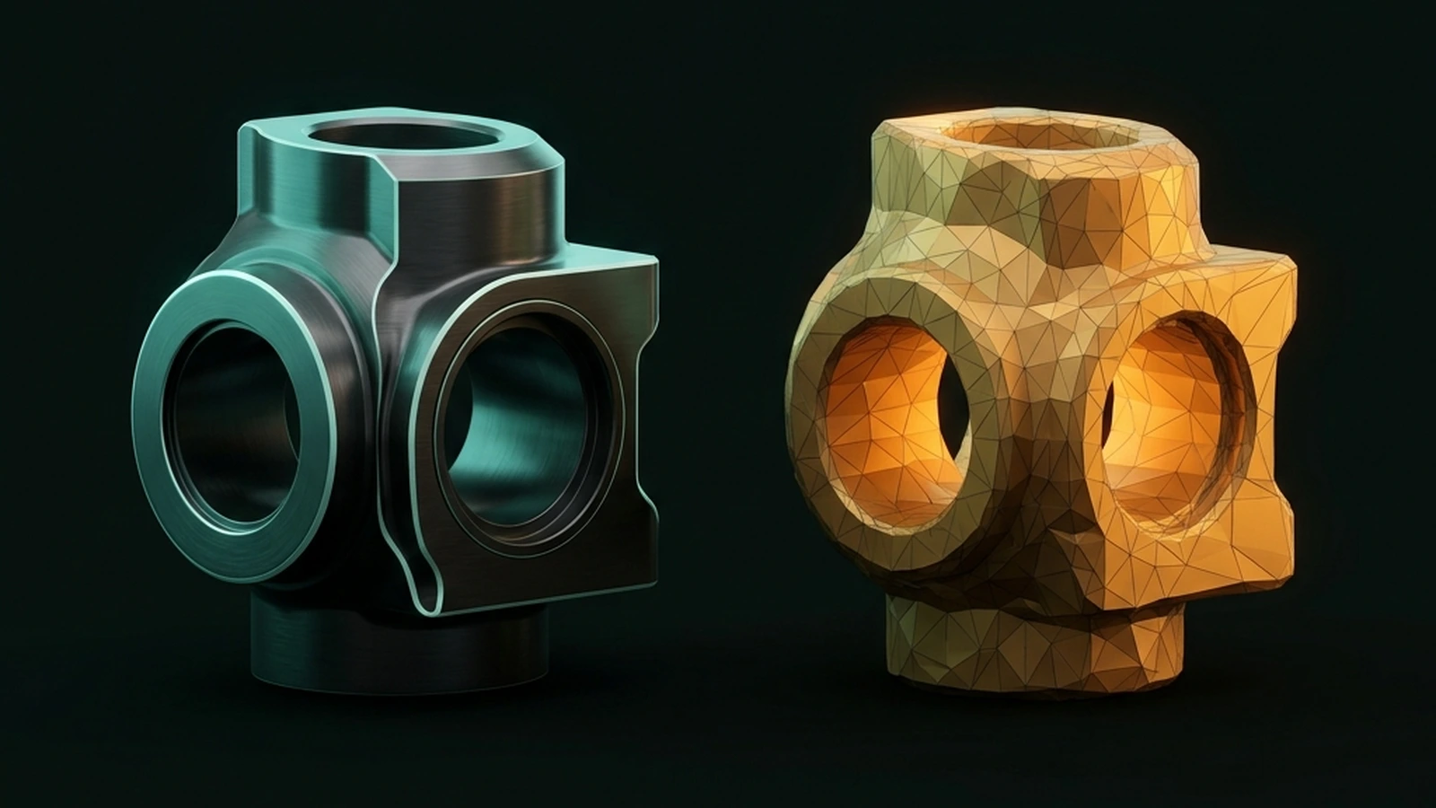
STEP (ISO 10303) stores B-Rep geometry: exact mathematical surfaces (planes, cylinders, splines) bounded by exact edges, plus the topology describing how they connect into a solid. STL stores a mesh: the same shape approximated as a list of flat triangles, with no dimensional exactness and no concept of "this is a hole" or "this is a fillet" — just triangle vertices.
The approximation has a name: chordal (or chord) deviation — the maximum distance from a curved
CAD surface to the flat triangle that replaces it. ASME/ISO tessellation modules even define
chordal_deviation as an explicit accuracy parameter for tessellated shape representations
(see ISO/TS 10303-1819 tessellated geometry).
Tighter chordal tolerance → more triangles → larger files; looser tolerance → facet marks visible
on CNC toolpaths and curved print surfaces. Peer-reviewed RP literature (e.g. Navangul, Paul & Anand,
ASME J. Manuf. Sci. Eng.) treats this CAD→STL conversion error
as a first-class manufacturing accuracy problem, not a cosmetic detail.
Side-by-side
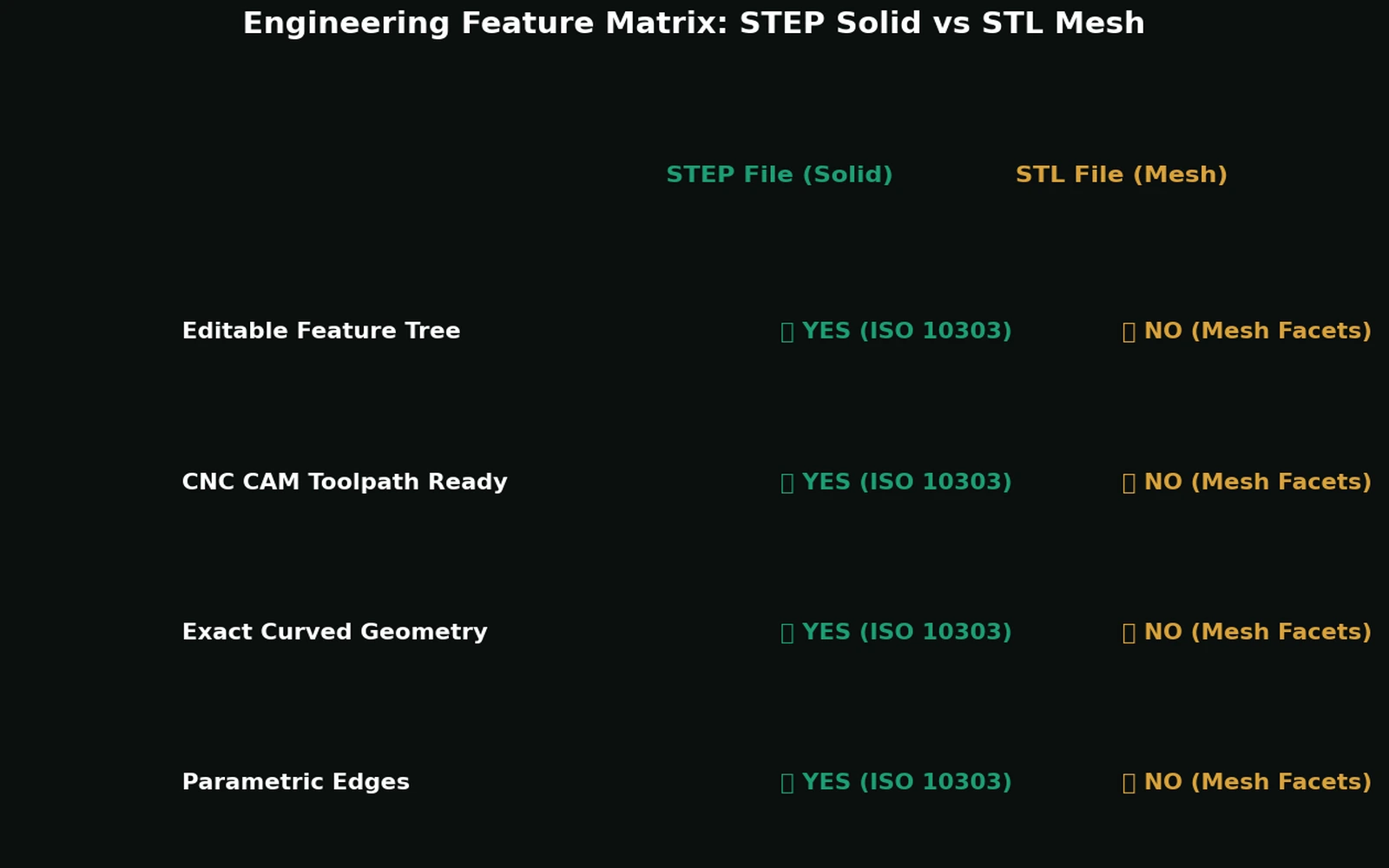
| STEP | STL | |
|---|---|---|
| Geometry type | B-Rep solid — exact surfaces + topology | Triangle mesh — faceted approximation |
| Edit dimensions afterward | Yes — change a parameter, geometry regenerates | Hard, usually destructive — requires manual triangle editing or full regeneration |
| Exact dimensional data | Yes, to the modeling kernel's precision | No — dimensions are estimated from triangle positions |
| CNC machining | Standard input format | Rarely used directly; toolpaths on mesh leave facet marks on curved surfaces |
| Injection mold tooling | Standard input format | Not suitable — tooling needs exact surfaces |
| 3D printing (FDM/SLA/SLS) | Needs conversion to mesh first (most slicers do this automatically) | Native, standard input format |
| Typical file size for curved geometry | Small — a cylinder is one parametric surface | Larger — a smooth curve needs many small triangles |
| Assembly structure (multi-part) | Can preserve part hierarchy and how parts connect | Usually flattens everything into one triangle soup |
The rule of thumb, expanded
- Quoting or ordering machined parts? STEP. Every CNC shop, injection molder, and casting vendor expects STEP (or a native CAD file) because their tooling needs exact surfaces, not triangle approximations.
- Slicing for FDM/SLA printing? STL can be enough — but if you'll need to edit the design later (change a hole size, add a mounting feature), keep the STEP file as your source of truth and export a fresh STL each time, rather than editing the STL directly.
- A supplier or colleague asks for "the CAD"? Assume STEP (or the native file), never STL — "send me the CAD" essentially never means "send me a mesh."
- Need to measure something precisely from a file someone sent you? If it's STL, treat any measurement as an approximation — you're measuring triangle vertex positions, not an exact stored dimension.
Where people get this wrong in practice
Sending STL to a machine shop. This is the most common mistake — the shop either has to manually reconstruct a solid from the mesh (time you're paying for) or asks you to resend as STEP. Avoid the round trip by exporting STEP from the start for anything headed to a CNC quote.
Editing an STL because "it's the only file I have." If you've lost the original parametric model and only have an STL, know that you're now working with an approximation — any edit will introduce additional faceting error on top of whatever the mesh already had. It's usually faster to rebuild the feature you need to change in a fresh CAD model than to hand-edit mesh triangles.
Assuming a fine mesh is "basically as good." A very high-resolution STL can look indistinguishable from a STEP file on screen. It still isn't dimensionally exact, and it still can't be parametrically edited — the visual similarity is exactly what makes this mistake easy to make and hard to notice until a downstream process (machining, tolerance analysis) needs the real thing.
How different are they, in numbers?
Abstract comparisons are easy to nod along to, so here is the concrete version for one simple part: a 60 mm plate with a single Ø20 mm through hole.
The STEP file describes that hole as one cylindrical surface with a radius of 10, trimmed by two circular edges. A handful of entities and numbers, exact forever.
The STL file describes the same hole as a ring of flat facets. How many depends on the export tolerance you chose, and so does the error:
| Facets around the hole | Effective diameter error | Practical read |
|---|---|---|
| 16 | ≈ 0.19 mm undersize | Visibly polygonal |
| 32 | ≈ 0.05 mm undersize | Looks round, still measurably wrong |
| 64 | ≈ 0.012 mm undersize | Fine for printing |
| 256 | ≈ 0.001 mm undersize | Large file, no practical gain |
The error is the sagitta — the gap between a chord and the arc it spans — and it shrinks roughly with the square of the facet count while the file grows linearly. You can chase it, but you never reach zero, and no facet count ever puts the number "20.000 mm" into the file for a machinist or an inspector to read back.
What each format does to the next process
CAM. A toolpath generated on a B-Rep cylinder follows the true surface. A toolpath generated on a faceted approximation follows the facets, which shows up as witness marks on the finished surface and uneven cutter engagement at the facet boundaries. This is why shops ask for STEP even when they can open your STL.
Inspection. A CMM programme compares measured points against nominal geometry. With STEP, the nominal is exact. With STL, the nominal is itself an approximation, so the comparison carries a built-in error you cannot separate from the manufacturing error.
Assembly. Mating requires selectable faces and axes. A mesh has neither, so components can be positioned but not constrained.
Editing. Changing a STEP hole from Ø20 to Ø22 is a normal CAD operation. Changing an STL hole means moving several hundred vertices, which nobody does.
What about 3MF?
If your reason for reaching for STL is 3D printing, 3MF is the better mesh format and worth knowing about. It is a compressed XML container that records units explicitly, supports colour, materials and multiple separate objects in one file, and so avoids the single largest source of mesh handoff errors — the fact that STL stores no unit at all. STL survives because every slicer reads it; use 3MF wherever the receiving end supports it. The wider format landscape is in CAD file formats explained, and export settings in generating STL files.
A short checklist before you export
- Will anyone need to change a dimension on this part later? → export STEP.
- Is this going to a CNC shop, mold maker, or caster? → export STEP.
- Is this only going to a 3D printer, and you have the STEP source safely kept elsewhere? → STL is fine for this specific handoff.
- Are you unsure? → export STEP. You can always convert STEP to STL later; going the other direction loses information permanently.
The bottom line
STL isn't a lesser format — it's the right format for a specific job (printing, visualization). The mistake is treating it as a general-purpose "3D model" substitute for STEP when the downstream use actually needs exact, editable geometry. When in doubt, keep STEP as your source of truth and generate STL only as a disposable export for the process that needs it.
Related reading: What is a STEP file? · B-Rep vs. mesh: why editable geometry matters · Colored STEP in CADAGEN · Open an assembly STEP in desktop CAD
Sources: ISO/TS 10303-1819 — Tessellated geometry / chordal deviation · Navangul, Paul & Anand — Error minimization in STL for layered manufacturing (ASME) · ISO 10303-242:2020.
Frequently asked questions
- What is the difference between STEP and STL?
- STEP stores exact boundary-representation geometry — a hole is a cylindrical face with a real radius. STL stores triangles that approximate the surface, with no units, no curves and no tolerances. STEP is for manufacturing and CAD exchange; STL is for 3D printing and quick visualisation.
- Can STL be converted back to STEP?
- Not reliably. A converter can wrap each triangle as a planar face, producing a technically valid but unusable STEP with tens of thousands of faces, or attempt surface recognition, which works on simple prismatic shapes and degrades quickly. Recovering a genuinely usable model means rebuilding it in CAD from the mesh as a reference — reverse engineering, not conversion.
- Which format should I send for 3D printing?
- STL is the universally accepted default and works everywhere. 3MF is technically better because it records units, colour, materials and multiple objects, which removes the entire class of unit-mismatch errors. Use 3MF when your slicer supports it, STL when you do not control the receiving end.
- Why did my STL come out the wrong size?
- The STL format stores no units. The numbers are dimensionless, and the millimetre convention is only a convention. A file exported in inches and read as millimetres arrives 25.4 times too small. State the unit in the filename, or use 3MF.