Python for CAD: From Install to Your First STEP File
A working walkthrough of scripted mechanical CAD in Python — environment setup, a parametric bracket, a generated part family, geometry tests in CI, and the mistakes that waste the first afternoon.
- Author:
- Cadagen
- Technical review:
- CADAGEN Engineering Team · Mechanical Engineer
- Last updated:
- August 15, 2026
- Sources:
- 3 primary references, listed below
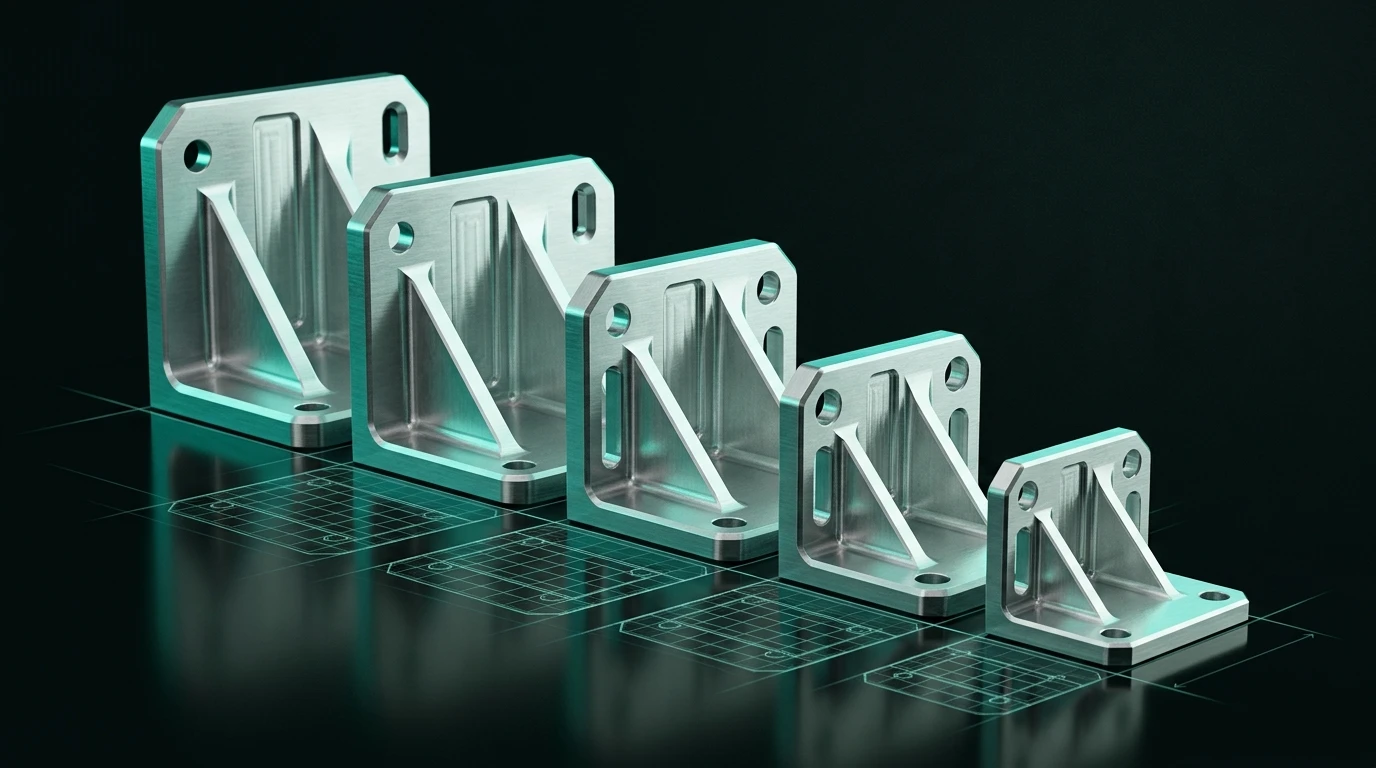
To produce CAD from Python you need a library that drives a boundary-representation kernel — build123d or CadQuery are the mainstream choices — and about twenty lines of code to get a real STEP file. This walkthrough goes from a clean machine to a parametric part, a generated family of sizes, and an automated geometry test.
If you are still weighing whether scripting is the right approach at all, read code CAD explained first. For choosing between the two libraries, see build123d vs CadQuery. The examples below use build123d; the same structure applies to CadQuery with different method names.
1. Set up an environment
Both libraries pull in large pre-built Open CASCADE bindings. Use an isolated environment — a broken kernel install is unpleasant to unpick from a system Python.
python -m venv .venv
source .venv/bin/activate        # Windows: .venv\Scripts\activate
pip install build123d
Expect a few hundred megabytes and a slow first install. Verify the kernel actually loaded before writing anything real:
from build123d import Box
print(Box(10, 10, 10).volume)    # 1000.0
If that prints 1000.0, the kernel bindings are working. If it raises an import error, the
problem is the environment, not your code — check the Python version against the library's
supported range before debugging anything else.
Pin the version. Both libraries have made breaking API changes between releases. Record the
version in requirements.txt so a script written today still produces the same geometry next
year.
2. Build one part with real parameters
The goal is not to make a box. It is to make a box whose dimensions are named, so the model can be changed by editing one value.
from build123d import *

# --- driving parameters -------------------------------------------------
length      = 90.0    # mm
width       = 50.0
thickness   = 8.0
hole_d      = 6.6     # clearance for M6
edge_dist   = 12.0
corner_r    = 6.0
# ------------------------------------------------------------------------

x = length / 2 - edge_dist
y = width / 2 - edge_dist

with BuildPart() as bracket:
    Box(length, width, thickness)
    fillet(bracket.edges().filter_by(Axis.Z), radius=corner_r)
    with Locations((x, y), (-x, y), (x, -y), (-x, -y)):
        Hole(radius=hole_d / 2)

export_step(bracket.part, "bracket.step")
export_stl(bracket.part, "bracket.stl")
Three details are load-bearing:
hole_d = 6.6, not6.0. A clearance hole has to be larger than the bolt. ISO 273 lists three series for M6: 6.4 mm (fine), 6.6 mm (medium) and 7.0 mm (coarse); medium is the normal default. Modelling the hole at the nominal thread diameter is one of the most common errors in generated CAD — see ISO metric thread sizes.filter_by(Axis.Z)instead of an index. Selecting "all edges parallel to Z" stays correct when the plate changes size.edges()[3]does not.bracket.part, notbracket. The builder context is not itself a solid. Passing the builder to an exporter produces a confusing error; passing.partworks.
3. See what you built
Editing geometry blind is the fastest way to give up on code CAD. Use a live viewer that
re-renders on save — ocp-vscode is the common choice for both build123d and CadQuery, and
Jupyter notebooks work well for exploratory sessions. Either way you want the loop to be save →
see, not save → export → open another application.
For a quick sanity check without any viewer at all, print the measurable properties:
part = bracket.part
print(part.volume)
print(part.bounding_box().size)
print(len(part.faces()), "faces", len(part.solids()), "solids")
If solids() returns more than one and you expected a single body, something in the script
produced disconnected geometry. That is worth catching before you look at a render, because a
disconnected part often looks correct.
4. Turn one part into a family
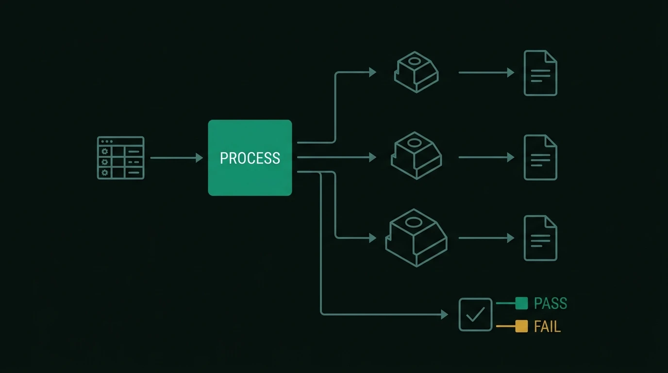
This is where scripting stops being a novelty and starts saving real time. A wrapper function plus a loop replaces forty save-as operations.
from pathlib import Path
from build123d import *

def bracket(length: float, width: float, thickness: float, hole_d: float):
    x, y = length / 2 - 12, width / 2 - 12
    with BuildPart() as part:
        Box(length, width, thickness)
        fillet(part.edges().filter_by(Axis.Z), radius=6)
        with Locations((x, y), (-x, y), (x, -y), (-x, -y)):
            Hole(radius=hole_d / 2)
    return part.part

SIZES = [
    ("M6",  90, 50,  8, 6.6),
    ("M8",  110, 60, 10, 9.0),
    ("M10", 130, 70, 12, 11.0),
]

out = Path("export")
out.mkdir(exist_ok=True)
for name, l, w, t, d in SIZES:
    export_step(bracket(l, w, t, d), out / f"bracket_{name}.step")
The same pattern reads sizes from a CSV, a database, or a supplier's dimension table instead of a hard-coded list — which is the actual reason to do this. More cases worth automating are in repetitive CAD tasks.
5. Test the geometry
A script that runs without raising an exception has not proven anything. Because the library runs headless, you can assert on the result the same way you would test any other function.
import pytest
from parts import bracket

def test_envelope():
    p = bracket(90, 50, 8, 6.6)
    size = p.bounding_box().size
    assert abs(size.X - 90) < 1e-6
    assert abs(size.Y - 50) < 1e-6
    assert abs(size.Z - 8) < 1e-6

def test_single_solid_with_material_removed():
    p = bracket(90, 50, 8, 6.6)
    assert len(p.solids()) == 1
    assert p.volume < 90 * 50 * 8          # holes and fillets removed material
    assert p.volume > 0.7 * 90 * 50 * 8    # but not a suspicious amount

@pytest.mark.parametrize("size", [(90, 50, 8, 6.6), (110, 60, 10, 9.0)])
def test_family_builds(size):
    assert bracket(*size).volume > 0
These four assertions catch the majority of silent failures: an empty solid, a boolean that removed the whole part, a doubled body, and an envelope that drifted. Run them in CI and a broken model fails the build instead of reaching a supplier.
Common first-afternoon mistakes
| Symptom | Cause | Fix |
|---|---|---|
| Exporter raises an attribute error | Passed the builder context, not the shape | Use part.part (or .sketch for 2D) |
| Fillet operation fails | Radius does not physically fit at some edge | Reduce the radius, or fillet in smaller groups |
| Model looks right, volume is zero | Boolean subtracted everything | Print volume after each step to find the culprit |
| Holes drift when a dimension changes | Positions hard-coded instead of derived | Express positions as expressions of the parameters |
| Part is 1000× too big in the slicer | Unit mismatch — STL carries no units | Confirm the consumer's unit assumption; see generating STL files |
| Selector picks the wrong face | Index-based or position-based selection | Filter by axis, geometry type or sorted position |
| Script works, script from last month does not | Library API changed between versions | Pin versions in requirements.txt |
Where to go next
- Assemblies. Place multiple parts with explicit locations and export a single STEP containing all bodies. Watch for in-place placement methods that mutate rather than copy — a shape positioned twice through the mutating variant becomes two references to one object.
- DFM checks in code. Minimum wall thickness, tool access, and draft can be checked programmatically before anyone opens the file. The rules themselves are in DFM 101.
- Standard parts. Do not model a bolt from scratch; reference the designation and use a library or catalogue geometry, as argued in generating fasteners, gears and bearings.
- Generation from a description. Once a part is a function of parameters, the remaining question is where those parameters come from — a form, a spreadsheet, or a natural-language description, as covered in how LLMs generate CAD.
The bottom line
Python CAD is a short on-ramp with a slow install: a virtual environment, one library, and about twenty lines gets you an exact STEP file. The value shows up on the second part, not the first — parameterise deliberately, select geometry by rule, assert on volume and bounding box, and pin your library version so the script still means the same thing next year.
Frequently asked questions
- How do I create a STEP file with Python?
- Install a B-Rep-backed CAD library such as build123d or CadQuery, build the solid from primitives and operations, then call the library's STEP exporter — export_step(part, 'part.step') in build123d, or cq.exporters.export(part, 'part.step') in CadQuery. Both write an ISO 10303 STEP file containing exact geometry, which any mechanical CAD system can open.
- Which Python CAD library should a beginner start with?
- build123d if you are starting fresh and expect to maintain the code, because operations are explicit statements rather than a chained selection stack. CadQuery if you are following an existing tutorial or company script. Both drive the same Open CASCADE kernel, so the geometry you can produce is equivalent.
- Can I run Python CAD without a CAD application installed?
- Yes. Libraries like build123d and CadQuery ship pre-built Open CASCADE bindings and run in a plain Python process with no CAD seat, no licence and no GUI. That is what makes them usable on a build server, in a container, or inside a larger automation pipeline.
- How do I check that a generated part is correct?
- Assert on measurable properties in a test: bounding box dimensions against the intended envelope, volume within an expected range, body count equal to one for a single solid, and — for printed parts — that the exported mesh is watertight. These checks catch the common silent failures where a script runs successfully but produces an empty, doubled or disconnected shape.