How LLMs Actually Generate CAD: Code, Not Geometry
Language models do not emit solids. They emit a program or a structured spec that a geometry kernel executes — which explains both why AI CAD works at all and exactly where it fails.
- Author:
- Cadagen
- Technical review:
- CADAGEN Engineering Team · Mechanical Engineer
- Last updated:
- August 15, 2026
- Sources:
- 3 primary references, listed below
A language model does not produce a solid. It produces a program — or a structured specification — and a geometry kernel produces the solid. Understanding that indirection explains most of what is confusing about AI CAD: why it can nail a flanged shaft coupling and then invent a bolt that does not exist, why the same prompt can fail twice and succeed on the third try, and why the useful engineering questions are about the verification layer rather than the model.

The three architectures
There are broadly three ways a machine-learning system can turn a description into 3D geometry. They are not equally suitable for mechanical work.
1. Direct geometry generation
The model outputs the shape itself — a mesh, a signed distance field, a voxel grid, or a neural implicit surface. This is what text-to-3D tools do, and it is genuinely impressive for characters, props and organic forms.
For mechanical parts it fails at the first requirement: there is no exact 12 mm hole anywhere in the output, only a shape that resembles one. Nothing downstream — CAM, tolerancing, mating — works on an approximation. This is the distinction covered in text-to-CAD vs text-to-3D.
2. Feature-sequence generation
The model emits a sequence of CAD commands — sketch, extrude, fillet, hole — in a structured format that a kernel replays. This is the approach behind several research systems trained on construction-sequence datasets.
It produces genuinely parametric output and matches how CAD actually works. Its limitation is data: the vocabulary is narrow, the public training corpora are small, and coverage outside the distribution of the training set degrades quickly.
The scale is worth stating concretely, because it explains a lot. The ABC dataset (Koch et al., CVPR 2019) holds roughly one million CAD models — but as B-Rep geometry only, with no record of how they were built. The Fusion 360 Gallery reconstruction subset (Willis et al., ACM TOG 2021) does carry construction sequences, and contains 8,625 of them. DeepCAD (Wu et al., ICCV 2021) was created specifically because that was too small, and reached 178,238 models with command sequences — by parsing Onshape designs and discarding every model that used operations beyond sketch and extrude. That last detail is the honest summary of the field: the largest sequence-level CAD corpus is built from the simplest possible subset of CAD.
3. Code generation into a kernel
The model writes a program in a real scripting API — a Python CAD library, a vendor API, or a domain-specific language — and that program is executed to build the part. This is the dominant production architecture, and for a specific reason: language models are extremely good at writing code and comparatively poor at everything else in this list.
The full picture of that scripting layer is in code CAD explained.
Why code generation wins in practice
| Direct geometry | Feature sequence | Code generation | |
|---|---|---|---|
| Output exactness | Approximate mesh | Exact (kernel-built) | Exact (kernel-built) |
| Editable afterwards | No | Yes | Yes — named parameters |
| Inspectable before delivery | Only visually | Partially | Fully — it is source code |
| Failure detectable automatically | Hard | Moderate | Easy — it either runs or raises |
| Training data availability | Large (general 3D) | Small | Very large (general code) |
| Handles novel part types | Poorly for mechanical | Poorly outside distribution | Reasonably, by composing operations |
| Typical failure | Plausible but unmeasurable shape | Invalid or truncated sequence | Script errors, or valid script with wrong geometry |
The third column's failure mode is the important one, and it deserves precision: a script that runs successfully is not a script that produced the right part. Executability proves syntax, not engineering. That gap is where the entire verification problem lives.
The pipeline, end to end
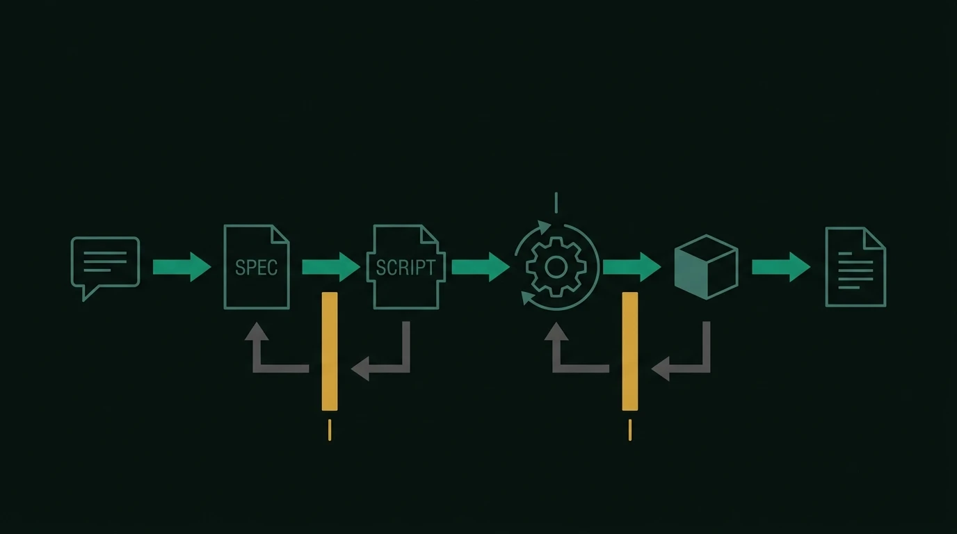
A production text-to-CAD system is mostly not the model. A representative flow:
- Intent extraction. Parse the request into a structured specification: part type, primary dimensions, features and their positions, material and process hints, standard-part designations. This step is where ambiguity gets caught — "a bracket about 100 mm long" has to become either a number or an explicit question.
- Adequacy check. Is there enough information to build anything? A description with no dimensions at all needs either a clarifying question or explicitly-labelled assumptions.
- Script generation. The model writes the program against a constrained API surface, usually with in-context examples of the exact idioms that are known to work.
- Static validation. Before running anything: are the imports allowed, does the script call only permitted operations, is it structurally complete rather than truncated mid-function.
- Execution in a sandbox. Run the script against the kernel. Syntax errors, unsupported operations and kernel failures surface here as exceptions.
- Geometric validation. Is the result a closed solid? Is the volume non-zero? Does the bounding box match the requested envelope? Are there disconnected bodies floating in space? Are wall thicknesses above the process minimum? These are deterministic checks, not model judgements.
- Semantic validation. Render the solid from several angles and check — with a vision model, a rule set, or a human — whether it actually depicts what was asked for. A perfectly valid solid can still be the wrong part.
- Repair loop. On failure, feed the specific error back and regenerate. Bounded, because an unbounded loop burns compute and rarely converges.
- Export. STEP for manufacturing, plus a mesh for preview.
Steps 4 through 8 are the majority of the engineering work, and the majority of what separates a demo from a tool. See what actually breaks for the failure taxonomy those steps are catching.
Why the same prompt gives different results
Language models are sampled, not evaluated. Temperature, tokenisation, context and the ordering of in-context examples all shift the output. Two consequences follow.
Non-determinism is real. The same description can produce a slightly different script twice. If the geometry is validated properly, both outputs are valid parts; the dimensions that were specified will match, and the ones that were assumed may differ. This is why a well-behaved tool reports which dimensions were given and which were assumed.
Best-of-N is a legitimate strategy. Generating several candidates and selecting the one that passes the most checks measurably improves output quality — at a proportional cost in compute and latency. Whether that trade is worth making depends on whether the user is exploring or finalising.
What the model is actually bad at
Being specific here is more useful than general scepticism.
- Arithmetic on dimensions. Deriving a bolt circle from a flange OD and an edge distance is a calculation, and models make arithmetic slips. Robust systems compute derived dimensions in the script rather than asking the model to pre-compute them.
- Standard part values. The clearance hole for an M6 bolt is 6.6 mm in ISO 273's medium series — not 6 mm, and not the same in the fine (6.4) and coarse (7.0) series. A model that "remembers" a table is less reliable than a lookup — argued at length in generating fasteners, gears and bearings.
- Spatial reasoning in three dimensions. Whether a boss actually intersects the wall it is supposed to attach to is a geometric fact, not a linguistic one. This is why disconnected and floating bodies are such a persistent failure mode, and why the geometric validation step exists.
- Tolerancing. Models default to nominal dimensions with no fit information. See tolerances AI tools get wrong.
- Knowing what it does not know. A model will confidently produce a script for a part type it has never seen well-represented. Confidence is not a signal.
What this means when you evaluate a tool
The architecture explains what questions are worth asking:
- What is the intermediate representation? If there isn't one — if the tool goes straight to geometry — the output is probably a mesh.
- What is checked before delivery, deterministically? "The model is very good" is not an answer. Closed solid, non-zero volume, envelope match, minimum wall are answers.
- Which dimensions are exposed as parameters afterwards? A model you cannot adjust is a picture with a file extension. See parametric CAD.
- What happens on failure? Silent delivery of a broken file is worse than an explicit error.
- Does it distinguish given from assumed dimensions? If everything is presented with equal confidence, you have to re-verify everything.
The bottom line
AI CAD works because language models write code well, and a kernel — not the model — builds the geometry. That indirection is a feature: it makes output exact, editable and automatically checkable. It also means the model is the least interesting part of a good system. Judge these tools by their verification layer, not by their demo render, and treat every generated model as a starting point to be reviewed rather than a finished engineering deliverable.
Frequently asked questions
- Do large language models generate 3D geometry directly?
- Almost never for mechanical CAD. The dominant architecture is indirect: the model produces a script or a structured specification, and a geometry kernel executes it to build the solid. Direct geometry generation exists in research and in mesh-focused tools, but it produces approximate surfaces rather than exact boundary representation, which is unusable for machining.
- Why do AI CAD tools generate code instead of a model file?
- Three reasons. Language models are trained overwhelmingly on text and code, so they are far more accurate at producing a valid program than valid B-Rep topology. A script can be validated by running it, so failures are detectable before delivery. And a script carries named parameters, so the resulting model stays editable instead of being a frozen shape.
- What training data exists for AI CAD?
- Public datasets are much smaller than in vision or language. Widely used examples include ABC (a large collection of CAD models with B-Rep data), the Fusion 360 Gallery dataset (with construction sequences), and DeepCAD (command sequences for parametric models). Compared with the billions of images or trillions of text tokens used elsewhere, mechanical CAD is a data-poor domain, which is a real constraint on how well these systems generalise.
- Can an LLM verify its own CAD output?
- Not on its own — a model's confidence is uncorrelated with whether the geometry is manufacturable. Verification has to come from deterministic checks that run outside the model: does the script execute, is the solid closed and non-empty, is the bounding box within the requested envelope, are wall thicknesses above the process minimum. A second model reviewing rendered views can catch some semantic errors, but it supplements deterministic checks rather than replacing them.
References
- Koch et al., ABC: A Big CAD Model Dataset for Geometric Deep Learning (CVPR 2019) — CVPR / NYU
- Willis et al., Fusion 360 Gallery: A Dataset and Environment for Programmatic CAD Construction (ACM TOG 40:4, 2021) — ACM Transactions on Graphics
- Wu, Xiao and Zheng, DeepCAD: A Deep Generative Network for Computer-Aided Design Models (ICCV 2021) — ICCV